


– 24 –
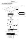
6. CHECK PRIOR TO REPAIRS
These checks are performed before replacing parts according to
“approximate specifications” to determine the faulty locations. For
details, refer to “Checks Prior to Parts Replacement and Adjust-
ments” (See page 8).
6-1. Temperature Compensation Offset Check
When performing adjustments, set the internal temperature and
room temperature of 22 °C to 28 °C.
Checking Procedure:
1. Turn the [AMS] knob to display “TEMP CHECK”
(C01).
2. Press the [YES] button.
3. “T=@@(##) [OK” should be displayed. If “T=@@ (##) [NG”
is displayed, it means that the results are bad.
(@@ indicates the current value set, and ## indicates the value
written in the non-volatile memory)
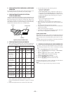
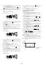
6-2. Laser Power Check
Before checking, check the IOP value of the optical pick-up.
(Refer to 5-8. Recording and Displaying IOP Information)
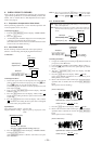
Connection :
Checking Procedure:
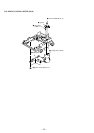
1. Set the laser power meter on the objective lens of the optical
pick-up. (When it cannot be set properly, press the 0 but-
ton or ) button to move the optical pick-up)
Connect the digital volt meter to CN110 pin 5 (I+3V) and
CN110 pin 4 (IOP).
2. Then, turn the
[AMS] knob and display “LDPWR
CHECK” (C02).
3. Press the [YES] button once and display “LD 0.9 mW $ ”.
Check that the reading of the laser power meter become 0.84
to 0.92 mW.
4. Press the [YES] button once more and display “LD 7.0 mW $
”. Check that the reading the laser power meter and digital
volt meter satisfy the specified value.
Specification:
Laser power meter reading: 7.0 ± 0.2 mW
Digital voltmeter reading : Optical pick-up displayed value
±10%
5. Press the [MENU/NO] button and display “LDPWR CHECK”
and stop the laser emission.
(The [MENU/NO] button is effective at all times to stop the
laser emission)
±
≠
Optical pick-up
objective lens
laser
power mete
r
+
–
BD board
digital voltmete
r
CN110 pin
5
(I +3V)
CN110 pin
4
(IOP)
[]
[]
±
≠
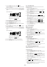
KMS260A
27X40
B0825
lOP=82.5 mA in this case
lOP (mA) = Digital voltmeter reading (mV)/1 (
Ω
)
(Optical pick-up label)
Note 1: After step 4, each time the [YES] button is pressed, the display
will be switched between “LD 0.7 mW $ ”, “LD 6.2 mW $
”, and “LD Wp $ ”. Nothing needs to be performed
here.
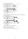
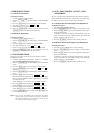
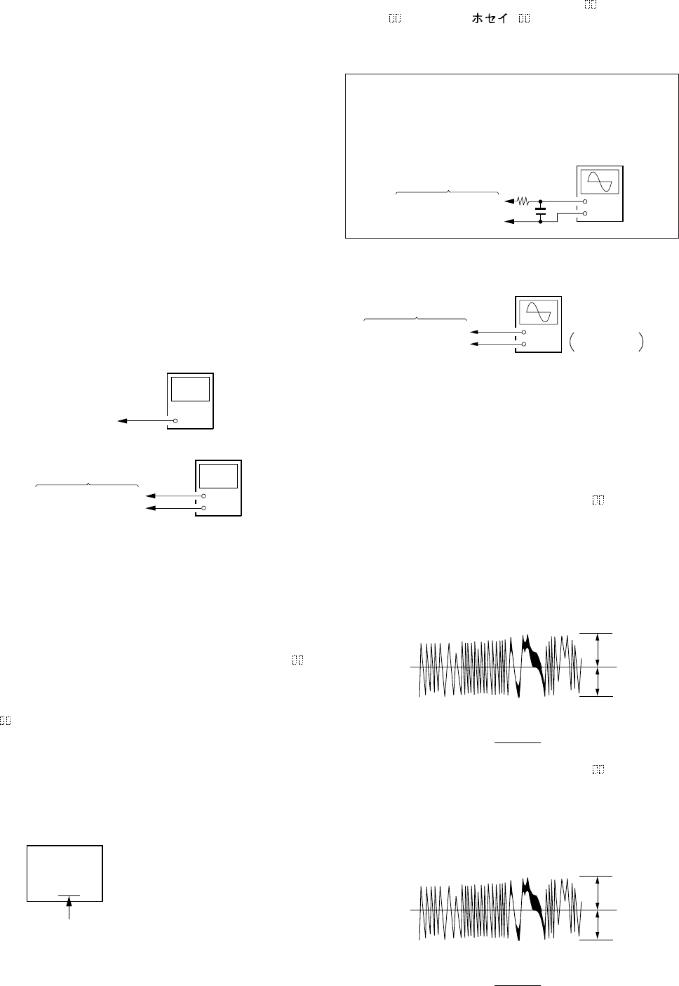
6-3. Traverse Check
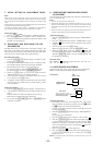
Connection :
Checking Procedure:
1. Connect an oscilloscope to CN110 pin 3 (TEO) and CN110
pin 1 (VC) of the BD board.
2. Load a disc (any available on the market). (Refer to Note 1)
3. Press the ) button and move the optical pick-up outside
the pit.
4. Turn the [AMS] knob and display “EF MO
CHECK”(C03).
5. Press the
[YES] button and display “EFB = MO-R”.
(Laser power READ power/Focus servo ON/tracking servo
OFF/spindle (S) servo ON)
6. Observe the waveform of the oscilloscope, and check that the
specified value is satisfied. Do not turn the[AMS]
knob.
(Read power traverse checking)
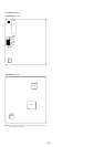
(Traverse Waveform)
7. Press the [YES] button and display “EFB = MO-W”.
8. Observe the waveform of the oscilloscope, and check that the
specified value is satisfied. Do not turn the [AMS]
knob.
(Write power traverse checking)
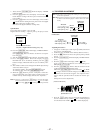
(Traverse Waveform)
+
–
oscilloscope
(DC range)
V: 0.1 V/div
H: 10 ms/div
BD board
CN110 pin
3
(TEO)
CN110 pin
1
(VC)
[]
±
≠
±
≠
A
B
VC
Specified value : Below 10% offset value
Offset value (%) = X 100
I
A – B
I
2 (A + B)
A
B
VC
Specified value : Below 10% offset value
Offset value (%) = X 100
I
A – B
I
2 (A + B)
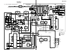
±
≠
+
–
oscilloscope
(DC range)
10 pF
330 k
Ω
CN110 pin
3
(TEO)
CN110 pin
1
(VC)
BD board
Note 1:Data will be erased during MO reading if a recorded disc is
used in this adjustment.
Note 2:If the traverse waveform is not clear, connect the oscilloscope
as shown in the following figure so that it can be seen more
clearly.