


182 mm
53 mm
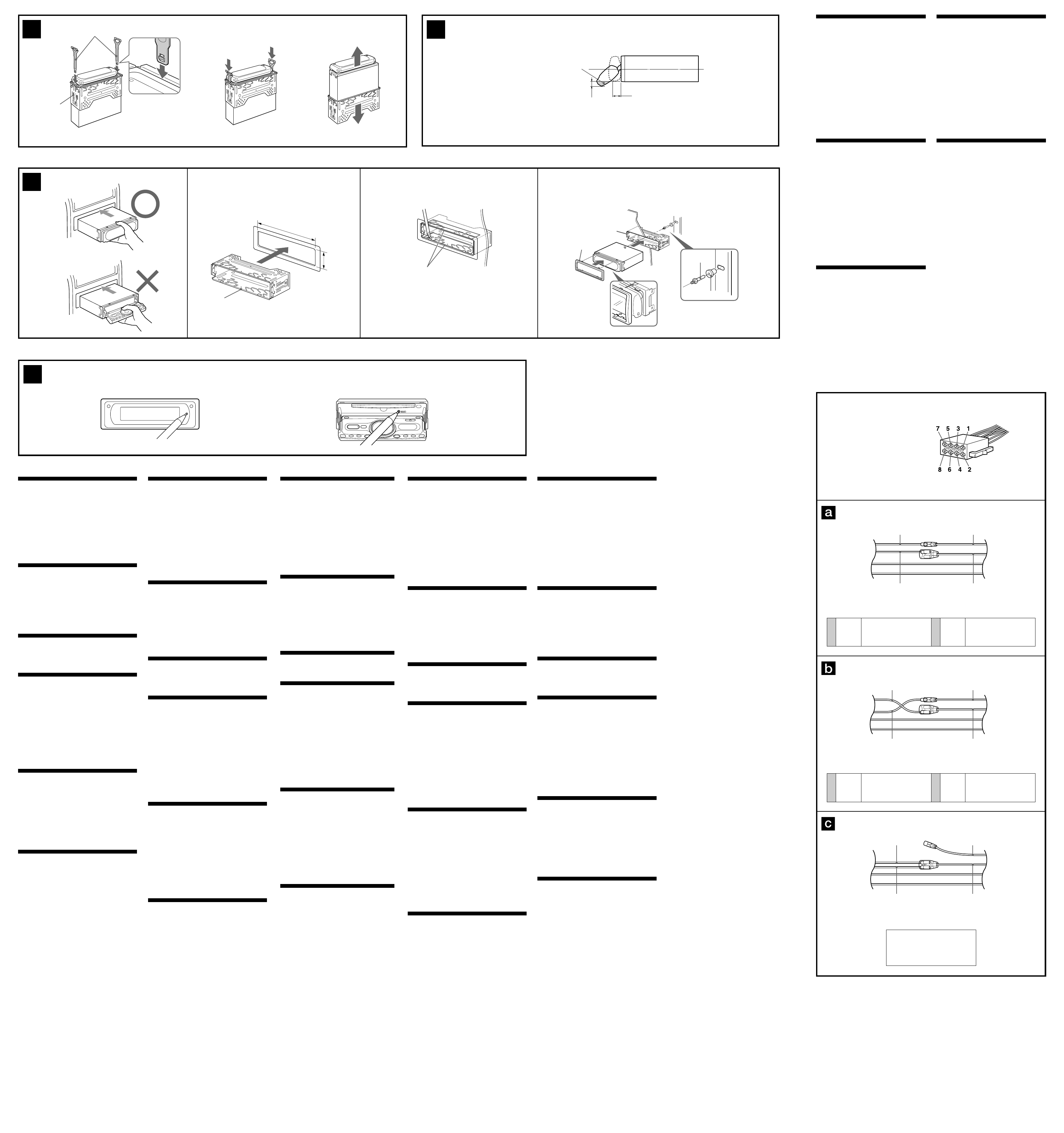
Power connection diagram
Auxiliary power connector may vary depending on
the car. Check your car’s auxiliary power connector
diagram to make sure the connections match
correctly. There are three basic types (illustrated
below). You may need to switch the positions of the
red and yellow leads in the car stereo’s power
connecting cord.
After matching the connections and switched
power supply leads correctly, connect the unit to
the car’s power supply. If you have any questions
and problems connecting your unit that are not
covered in this manual, please consult the car
dealer.
Auxiliary power connector
Hilfsstromanschluss
Connecteur d’alimentation auxiliaire
Connettore di alimentazione accessoria
Hulpvoedingsaansluiting
4
Yellow
Gelb
Jaune
Giallo
Geel
continuous power supply
permanente Stromversorgung
alimentation continue
alimentazione continua
continu voeding
the car without ACC position
Fahrzeug ohne Zubehörposition (ACC)
Voiture sans position ACC
macchina priva di posizione ACC
auto zonder ACC stand
Red
Rot
Rouge
Rosso
Rood
Red
Rot
Rouge
Rosso
Rood
Yellow
Gelb
Jaune
Giallo
Geel
Yellow
Gelb
Jaune
Giallo
Geel
Red
Rot
Rouge
Rosso
Rood
switched power supply
geschaltete Stromversorgung
alimentation commutée
alimentazione commutata
geschakelde voeding
7
4
Yellow
Gelb
Jaune
Giallo
Geel
switched power supply
geschaltete Stromversorgung
alimentation commutée
alimentazione commutata
geschakelde voeding
Red
Rot
Rouge
Rosso
Rood
Red
Rot
Rouge
Rosso
Rood
Yellow
Gelb
Jaune
Giallo
Geel
Yellow
Gelb
Jaune
Giallo
Geel
Red
Rot
Rouge
Rosso
Rood
continuous power supply
permanente Stromversorgung
alimentation continue
alimentazione continua
continu voeding
7
Red
Rot
Rouge
Rosso
Rood
Red
Rot
Rouge
Rosso
Rood
Yellow
Gelb
Jaune
Giallo
Geel
Yellow
Gelb
Jaune
Giallo
Geel
Voedingsaansluitschema
De hulpvoedingsaansluiting kan verschillen
afhankelijk van de auto. Controleer het
voedingsaansluitschema dat bij dit apparaat wordt
geleverd om te zien of de aansluitingen kloppen. Er
zijn drie basistypes (zie illustratie hieronder). Het is
mogelijk dat u de posities van de rode en gele
kabels in het aansluitsnoer van het auto-
audiosysteem moet omwisselen.
Als de aansluitingen en geschakelde
voedingskabels kloppen, sluit u het apparaat aan
op de voeding van de auto. Indien u nog vragen of
problemen hebt in verband met het aansluiten van
het apparaat die niet in deze handleiding vermeld
staan, raadpleegt u de autodealer.
Schema dei collegamenti di
alimentazione
Il connettore di alimentazione accessoria può
variare a seconda della macchina. Controllare il
diagramma del connettore di alimentazione
accessoria della macchina per essere sicuri che i
collegamenti corrispondano correttamente. Vi sono
tre tipi di base (illustrazione sotto). Potrà essere
necessario cambiare le posizioni dei fili rosso e
giallo nel cavo di alimentazione dello stereo della
macchina.
Dopo aver fatto corrispondere i collegamenti e aver
commutato i fili di alimentazione, collegare
l’apparecchio all’alimentazione della macchina. Se
si hanno domande o se sorgono problemi che non
sono stati trattati nel manuale relativi ai
collegamenti dell’apparecchio, contattare
l’autoconcessionario.
Schéma de connexion
d’alimentation
Le connecteur d’alimentation auxiliaire peut varier
suivant le type de voiture. Vérifiez le schéma du
connecteur d’alimentation auxiliaire de votre
voiture pour vous assurer que les connexions
correspondent. Il en existe trois types de base
(illustrés ci-dessous). Il se peut que vous deviez
commuter la position du fil rouge et jaune du
cordon d’alimentation de l’autoradio.
Après avoir établi les connexions et commuté
correctement les fils d’alimentation, raccordez
l’appareil à l’alimentation de la voiture. Si vous
avez des questions ou des difficultés à propos de
cet appareil qui ne sont pas abordées dans le
présent mode d’emploi, consultez votre
concessionnaire automobile.
Stromanschlussdiagramm
Der Hilfsstromanschluss kann je nach Fahrzeugtyp
unterschiedlich sein. Sehen Sie im
Hilfsstromanschlussdiagramm für Ihr Fahrzeug
nach, wie die Verbindung ordnungsgemäß
vorgenommen werden muss. Es gibt, wie unten
abgebildet, drei grundlegende Typen.
Sie müssen möglicherweise die rote und gelbe
Leitung des Stromversorgungskabels der
Autostereoanlage vertauschen.
Stellen Sie die Anschlüsse her, schließen Sie die
geschalteten Stromversorgungsleitungen richtig an
und verbinden Sie dann das Gerät mit der
Stromversorgung Ihres Fahrzeugs. Wenn beim
Anschließen des Geräts Fragen oder Probleme
auftreten, die in dieser Bedienungsanleitung nicht
erläutert werden, wenden Sie sich bitte an den
Autohändler.
Précautions
•Choisir soigneusement l’emplacement de
l’installation afin que l’appareil ne gêne pas la
conduite normale du véhicule.
•Eviter d’installer l’appareil dans un endroit exposé à
de la poussière, de la saleté, des vibrations violentes
ou à des températures élevées, comme en plein
soleil ou à proximité d’une bouche d’air chaud.
•Pour garantir un montage sûr, n’utiliser que le
matériel de montage fourni.
Réglage de l’angle de montage
Ajuster l’inclinaison à un angle inférieur à 45°.
Retrait du support (4)
Avant d’installer l’appareil, retirez le support 1
de l’appareil.
1 Insérez les deux clés de déblocage 7
simultanément entre l’appareil et le support 1
jusqu’au déclic indiquant qu’elles sont en place.
2 Tirez le support 1 vers le bas, puis tirez
l’appareil vers le haut pour les séparer.
Partie saillante de la façade (
5
)
Exemple de montage (6)
Installation dans le tableau de bord
Pendant l’installation de l’appareil, vérifiez que la
façade de cet appareil est fermée (6-
*
).
Si la façade est ouverte pendant l’installation et
qu’elle est soumise à une force trop importante, un
dysfonctionnement risque de se produire.
Remarques
• Plier ces griffes pour assurer une prise correcte si
nécessaire (6-2).
• Assurez-vous que les 4 taquets du tour de protection
4 sont correctement insérés dans les fentes de
l’appareil (6-3).
Avertissement en cas
d’installation dans une voiture
dont le contact ne comporte pas
de position ACC (accessoires)
Après avoir coupé le moteur, n’oubliez
pas de maintenir (OFF) sur l’appareil
enfoncée jusqu’à ce que l’affichage
disparaisse.
Sinon, l’affichage n’est pas désactivé et la batterie
se décharge.
Touche RESET (7)
Après avoir retiré la façade, une fois que l’installation
et les raccordements sont terminés, appuyez sur la
touche RESET avec un stylo à bille, etc.
Precautions
•Choose the installation location carefully so that the
unit will not interfere with normal driving operations.
•Avoid installing the unit in areas subject to dust, dirt,
excessive vibration, or high temperature, such as in
direct sunlight or near heater ducts.
•Use only the supplied mounting hardware for a safe
and secure installation.
Mounting angle adjustment
Adjust the mounting angle to less than 45°.
Removing the bracket (4)
Before installing the unit, remove the bracket 1
from the unit.
1 Insert both release keys 7 together between the
unit and the bracket 1 until they click.
2 Pull down the bracket 1, then pull up the unit to
separate.
Extended portion of the front
panel (5)
Mounting example (6)
Installation in the dashboard
When installing this unit, be sure to close the front
panel of the unit (6-
*
).
If the front panel is opened while installing and given
too much force, it may cause a malfunction.
Notes
• Bend these claws outward for a tight fit, if necessary
(6-2).
• Make sure that the 4 catches on the protection collar
4 are properly engaged in the slots of the unit (6-3).
Warning when installing in a car
without ACC (accessory) position
on the ignition key switch
After turning off the ignition, be sure to
press and hold (OFF) on the unit until the
display disappears.
Otherwise, the display does not turn off and this
causes battery drain.
RESET button (7)
When the installation and connections are completed, be
sure to press the RESET button with a ballpoint pen, etc.
Vorsichtsmaßnahmen
•Wählen Sie den Einbauort sorgfältig so aus, dass das
Gerät beim Fahren nicht hinderlich ist.
•Bauen Sie das Gerät so ein, dass es keinen hohen
Temperaturen (keinem direkten Sonnenlicht, keiner
Warmluft von der Heizung), keinem Staub, keinem
Schmutz und keinen starken Vibrationen ausgesetzt
ist.
•Für eine sichere Befestigung verwenden Sie stets nur
die mitgelieferten Montageteile.
Hinweis zum Montagewinkel
Das Gerät sollte in einem Winkel von weniger als 45°
montiert werden.
Abnehmen der Halterung (4)
Bevor Sie das Gerät installieren, nehmen Sie bitte
die Halterung 1 vom Gerät ab.
1 Führen Sie beide Löseschlüssel 7 zwischen dem
Gerät und der Halterung 1 ein, bis sie mit einem
Klicken einrasten.
2 Ziehen Sie die Halterung 1 nach unten und das
Gerät nach oben, um die beiden zu trennen.
Überstehender Teil der Frontplatte
(5)
Montagebeispiel (6)
Installation im Armaturenbrett
Achten Sie beim Einbau des Geräts darauf, die
Frontplatte geschlossen zu halten (6-
*
).
Wenn sich die Frontplatte beim Einbau öffnet und Sie zu
stark darauf drücken, kann es zu einer Fehlfunktion
kommen.
Hinweise
• Falls erforderlich, biegen Sie diese Klammer für einen
sicheren Halt nach außen (6-2).
• Achten Sie darauf, die 4 Verriegelungen an der
Schutzumrandung 4 korrekt in die Aussparungen am
Gerät einzusetzen (6-3).
Warnhinweis zur Installation des
Geräts in einem Auto mit
Zündschloss ohne Zubehörposition
ACC oder I
Nachdem Sie die Zündung ausgeschaltet
haben, halten Sie am Gerät unbedingt
(OFF) gedrückt, bis die Anzeige
ausgeblendet wird.
Andernfalls wird die Anzeige nicht ausgeschaltet
und der Autobatterie wird Strom entzogen.
Taste RESET (7)
Wenn Sie das Gerät eingebaut und alle Anschlüsse
vorgenommen haben, müssen Sie mit einem
Kugelschreiber oder einem anderen spitzen Gegenstand
die Taste RESET drücken.
Voorzorgsmaatregelen
•Kies de installatieplaats zorgvuldig zodat het apparaat
de bestuurder niet hindert tijdens het rijden.
•Installeer het apparaat niet op plaatsen waar het
blootgesteld wordt aan hoge temperaturen, b.v. in
direct zonlicht of bij de warme luchtstroom van de
autoverwarming, aan sterke trillingen, of waar het in
contact komt met veel stof of vuil.
•Gebruik voor het veilig en stevig monteren van het
apparaat uitsluitend de bijgeleverde montage-
onderdelen.
Maximale montagehoek
Installeer het apparaat nooit onder een hoek van meer
dan 45° met het horizontale vlak.
De beugel verwijderen (4)
Voordat u het apparaat gaat installeren, moet u
de beugel 1 van het apparaat verwijderen.
1 Plaats de ontgrendelingssleutels 7 tussen het
toestel en de beugel 1 tot deze vastklikken.
2 Trek de beugel 1 omlaag en trek het apparaat
omhoog om deze van elkaar te scheiden.
Verlengstuk van het frontpaneel
(5)
Montagevoorbeeld (6)
Montage in het dashboard
Bij het installeren van het apparaat dient het
frontpaneel te zijn gesloten (6-*).
Als het frontpaneel tijdens het installeren open is, kan
het worden geforceerd wat tot een defect kan leiden.
Opmerkingen
• Indien nodig kunt u deze klemhaken ombuigen voor
een steviger bevestiging (6-2).
• De 4 grepen op de beschermende rand 4 moeten
goed in de sleuven van het apparaat zijn geplaatst
(6-3).
Opgelet bij het monteren in een
auto waarvan het contactslot geen
ACC (accessory) stand heeft
Als de motor is uitgeschakeld, moet u op
(OFF) drukken en deze toets ingedrukt
houden tot de weergave verdwijnt.
Als u dit niet doet, wordt de weergave niet
uitgeschakeld en raakt de batterij uitgeput.
RESET-toets (7)
Na het installeren en verrichten van alle aansluitingen,
moet u de RESET toets indrukken met een balpen of
dergelijke.
Precauzioni
•Scegliere con attenzione la posizione per
l’installazione in modo che l’apparecchio non
interferisca con le operazioni di guida del conducente.
•Evitare di installare l’apparecchio dove sia soggetto ad
alte temperature, come alla luce solare diretta o al
getto di aria calda dell’impianto di riscaldamento, o
dove possa essere soggetto a polvere, sporco e
vibrazioni eccessive.
•Usare solo il materiale di montaggio in dotazione per
un’installazione stabile e sicura.
Regolazione dell’angolo di montaggio
Regolare l’angolo di montaggio in modo che sia
inferiore a 45°.
Rimozione della staffa (4)
Prima di installare l’apparecchio, rimuovere la
staffa 1 dall’apparecchio.
1 Inserire contemporaneamente entrambe le
chiavette di rilascio 7 tra l’apparecchio e la staffa
1 fino a che non scattano in posizione.
2 Estrarre la staffa 1, quindi sollevare
l’apparecchio per rimuovere la staffa.
Parte sporgente del pannello
anteriore (5)
Esempio di montaggio (6)
Installazione nel cruscotto
Durante l’installazione dell’apparecchio, assicurarsi
di chiudere il relativo pannello anteriore (6-
*
).
Se durante l’installazione il pannello anteriore è aperto e
viene esercitata eccessiva forza, è possibile che si
verifichino problemi di funzionamento.
Note
• Piegare verso l’esterno questi morsetti per
un’installazione più sicura, se necessario (6-2).
• Assicurarsi che i 4 fermi sulla cornice di protezione 4
siano correttamente inseriti negli alloggiamenti
dell’apparecchio (6-3).
Informazioni importanti per
quando si effettua l’installazione
su un’auto sprovvista della
posizione ACC (accessoria)
sull’interruttore di accensione
Dopo avere spento il motore, assicurarsi di
tenere premuto (OFF) sull’apparecchio
finché il display non scompare.
Diversamente, il display non viene disattivato e
questo potrebbe causare lo scaricamento della
batteria.
Tasto RESET (7)
Dopo aver terminato l’installazione e i collegamenti,
assicurarsi di premere il tasto RESET con la punta di
una penna a sfera e simili.
1
Dashboard
Armaturenbrett
Tableau de bord
Cruscotto
Dashboard
Fire wall
Motorraumtrennwand
Paroi ignifuge
Parete tagliafiamma
Brandschot
4
2
3
1
1
6
23
4
7
c
c
1
Face the hook inwards.
Der Haken muss nach innen weisen.
Tournez le crochet vers l’intérieur.
Con il gancetto rivolto verso l’interno.
Het haakje moet naar binnen wijzen.
claws
Klammern
griffes
Morsetti
klemhaken
4 5
6,8 mm
19,3 mm
*
7
Extended portion of the front panel
Überstehender Teil der Frontplatte
Partie saillante de la façade
Parte sporgente del pannello anteriore
Verlengstuk van het frontpaneel
Main-display position
Haupt-Display
Position fermée : écran d’affichage principal
Posizione del display principale
Hoofddisplaypositie
Sub-display position
Zusatz-Display
Position d’accès au panneau de commande
Posizione del display secondario
Subdisplaypositie