7
CDX-CA400/CA530X/CA580X
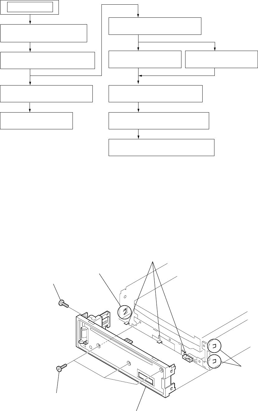
claws
4
claws
5
panel (1) assy, sub
3
claw
1
PTT 2.6x6
2
PTT 2.6x6
SECTION 2
DISASSEMBLY
Note : This set can be disassemble according to the following sequence.
Note : Follow the disassembly procedure in the numerical order given.
2-1. PANEL (1) ASSY, SUB
2-1. PANEL (1) ASSY, SUB
(Page 7)
2-2. CD MECHANISM BLOCK
(Page 8)
2-5. CHASSIS (T) SUB ASSY
(Page 9)
2-6. LEVER SECTION
(Page 10)
2-8. SHAFT ROLLER ASSY
(Page 11)
2-9. FLOATING BLOCK ASSY
(Page 11)
2-10. OPTICAL PICK-UP BLOCK
(Page 12)
SET
2-7. SERVO BOARD
(Page 10)
2-3. MAIN BOARD
(Page 8)
2-4. HEAT SINK
(Page 9)


