


2
SONANCE VISUAL PERFORMANCE
®
6” IN-CEILING
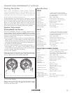
Stereo Placement (2-Channel)
• Place the left and right speakers anywhere from 6 feet to 10
feet apart, with the main listening position as close to midway
between the speakers as possible.
• In most cases pivoting the woofer of each speaker directly
towards the main listening position will help maximize the
stereo soundstage.
Use the Left and Right speaker placement in
Figures 2
and
3
(on page 1) as a guide.
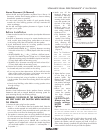
Before Installation
1. Determine the location for the speaker (see
Speaker Placement
on page 1).
2. Perform an obstruction survey to be certain that there are no
studs, conduit, pipes, heating ducts, pocket doors or air returns
in the ceiling cavity that will interfere with the speaker.
3. Visual Performance Series 6” in-ceiling speakers have the
following mounting space requirements:
• VP69R/VP67R/VP65R: 8
5
/
32
” (207mm) diameter mounting
hole with at least 5
3
/16” (132mm) depth within the mounting
cavity.
• VP65S/VP65STL: 8
5
/
32
” x 8
5
/
32
” (207mm x 207mm) mount-
ing hole. The VP65S requires at least 4
13
/16” (122mm) depth
within the mounting cavity; the VP65STL requires at least 3
1
/
32”
(77mm) depth within the mounting cavity.
• VP65RTL: 8
5
/32” diameter mounting hole with at least 3
1
/32”
(77mm) depth within the mounting cavity.
4. Position the included cutout template where the speaker is to
be located and pencil an outline on the ceiling.
• If you are unsure about obstructions, drill a small hole in the
center of the outline and insert a coat hanger wire into the
hole to feel-around for possible obstructions.
5. Cut the mounting hole using a keyhole or drywall saw, and
run the speaker wires from the mounting hole to the amplifier
location.
• Consult local building codes before running speaker wires
through ceilings.
Installation
Sonance Visual Performance Series speakers feature exclusive
FastMount
®
tabs and an integral RotoLock
®
mounting system for
quick mounting directly into existing ceilings.
WARNING: THE EDGES OF THE FASTMOUNT TABS
ARE VERY SHARP. USE CAUTION WHEN HANDLING
THE SPEAKER.
1. Remove the paint plug from the speaker.
2. Strip ¼” – ½” of insulation from each speaker lead. Twist the
strands or tin the exposed wire with solder to ensure that there
are no stray strands. (Stray strands that touch each other can
cause a short-circuit that can damage the amplifier.)
3. The speaker’s connector posts are spring-loaded. Push the top
of each connector post down to open the connector and insert
the exposed wires into the holes in the posts.
• The speaker’s positive post is labeled with a red dot; the
negative post is labeled with a black dot. Double-check that
you connected amplifier “+” to speaker “+” and amplifier “–”
to speaker “–”.
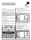
4. Make sure all the
RotoLock clamps are
retracted so that they
are tucked within the
mounting hole’s border.
Insert the speaker into
the hole in the ceiling
(
Figure 4
). The
RotoLock system can
accommodate a maxi-
mum ceiling material
thickness of 1¼”.
• The FastMount tabs
will prevent the
speaker from falling
out of the mounting
hole, allowing the
installer to let go of
the speaker to pick-up
tools or other items
(
Figure 5
).
NOTE: THE FASTMOUNT
TABS ARE DESIGNED
FOR ONE-TIME USE
ONLY. IF THE SPEAKER IS
REMOVED FROM THE
MOUNTING HOLE THE
FASTMOUNT TABS WILL
DISCONNECT AND
REMAIN INSIDE THE
CEILING.
5. Tighten the four screws
on the front of the
speaker baffle. The
RotoLock clamps will
automatically rotate
into position and begin
clamping the speaker
(
Figure 6
).
• When you notice
resistance on the
screws the speaker
has been clamped
successfully.
IMPORTANT:
Always use low-
torque settings;
NEVER over-
tighten.
NOTE: ADJUSTING THE TENSION OF THE ROTOLOCK CLAMPS
SO THAT THE SPEAKER FRAME IS FLAT WILL HELP ENSURE THAT
THE GRILLE CONTACTS THE CEILING ALL THE WAY AROUND THE
SPEAKER FOR A PROPER FIT.
6. The new micro flange grille is held in place by several small,
powerful magnets on the speaker frame. Place the grille
against the speaker and the magnets will hold it firmly in
place. When properly installed, the grille flange should make
contact with the wall all the way around the speaker.
FastMount Tabs
RotoLock Clamps
(retracted)
FIGURE 4: INSERTING THE SPEAKER
INTO THE MOUNTING HOLE
F
IGURE 5:
F
ASTMOUNT TABS
RotoLock Clamps
(extended)
FIGURE 6:
T
IGHTENING THE
R
OTOLOCK CLAMPS