


2
SONANCE SYMPHONY
®
TR & TSQ
Stereo (2-Channel)
• Place the left and right speakers anywhere from 6 feet to 10 feet apart, with
the main listening position as close to midway between the speakers as possible.
• In most cases pivoting the woofer of each speaker directly towards the main lis-
tening position will help maximize the stereo soundstage.
Use the left and right speaker placement in
Figures 3
and
4
(on page 1) as a guide.
Before Installation: Retrofit
1. Determine the location for the speaker (see
Speaker Placement
on page 1).
2. Perform an obstruction survey to be certain that there are no studs, conduit,
pipes, heating ducts, pocket doors or air returns in the ceiling cavity that will
interfere with the speaker.
3. The cutout for all SymphonyTR speakers is 8
5
/
32
” (207mm) — 8
5
/
32
”x 8
5
/
32
”
(207mm x 207mm) for TSQ speakers. There also must be at least 5
3
/
16
” (152mm)
depth within the ceiling cavity for TR-series speakers and 4
13
/
16
” (122mm) for
TSQ speakers.
4. Position the included cutout template where the speaker is to be located and
pencil an outline on the ceiling.
• If you are unsure about obstructions, drill a small hole in the center of
the outline and insert a coat hanger wire into the hole to feel-around for
possible obstructions.
5. Cut the mounting hole using a keyhole or drywall saw, and run the speaker
wires from the mounting hole to the amplifier location.
• Consult local building codes before running speaker wires through ceilings.
Installation
Sonance Symphony TR/TSQ speakers feature exclusive FastMount
®
tabs and an inte-
gral RotoLock
®
mounting system for quick mounting directly into existing ceilings.
WARNING: THE EDGES OF FASTMOUNT TABS ARE VERY
SHARP. USE CAUTION WHEN HANDLING THE SPEAKER.
1. Remove the paint plug from the speaker.
2. Run speaker wire from each speaker to the amplifier location.
3. Strip ¼” – ½” of insulation from each speaker lead. Twist the strands or tin
the exposed wire with solder to ensure that there are no stray strands.
(Stray strands that touch each other can cause a short-circuit that can damage
the amplifier.)
4. The speaker’s connector posts are spring-loaded. Push the top of each connector
post down to open the connector and insert the exposed wires into the holes
in the posts.
• The speaker’s positive post is labeled with a red dot; the
negative post is labeled with a black dot. Double-check that you connected
amplifier “+” to speak-
er “+” and amplifier
“–” to speaker “–”.
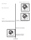
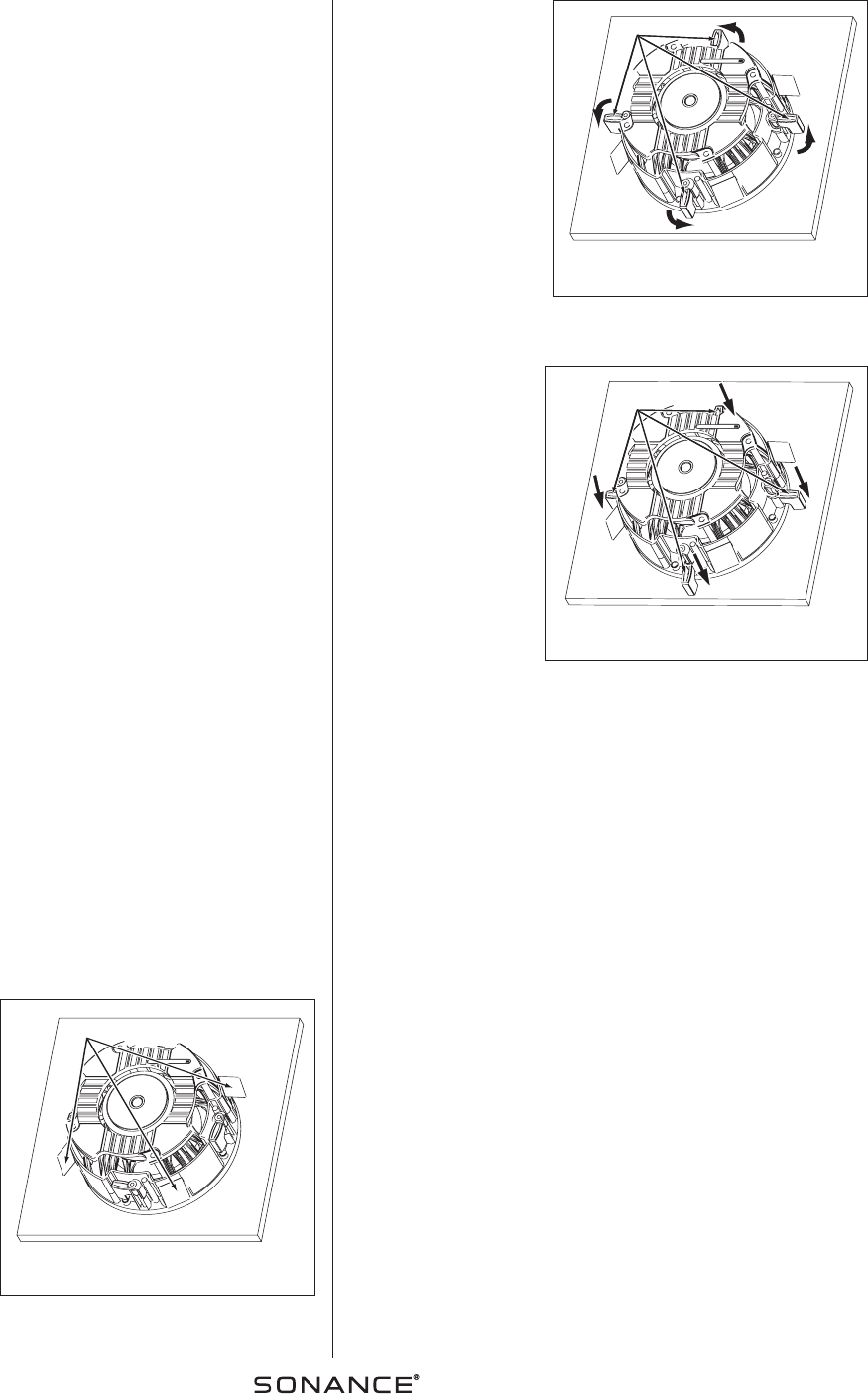
5. Make sure all the
RotoLock clamps are in
the full clockwise position
so that they are tucked
within the mounting hole’s
border. Insert the speaker
into the hole in the ceil-
ing (
Figure 5
). The
RotoLock system can
accommodate a maximum
ceiling material thickness
of 1¼”.
• The FastMount tabs will
prevent the speaker
from falling out of the
mounting hole, allowing
the installer to let go
of the speaker to pick-
up tools or other items
(
Figure 6
).
N
OTE
:T
HE
F
AST
M
OUNT
TABS ARE DESIGNED
FOR ONE
-
TIME USE
ONLY
.I
F THE SPEAK
-
ER IS REMOVED FROM
THE MOUNTING HOLE
THE
F
AST
M
OUNT TABS WILL DISCONNECT AND REMAIN INSIDE THE
CEILING
.
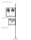
6. Tighten the four screws
on the front of the
speaker baffle. The
RotoLock clamps will
automatically rotate into
position and begin
clamping the speaker
(
Figure 7
).
• When you notice
resistance on the
screws the speaker has
been clamped
successfully.
IMPORTANT:
Always use low-torque settings; NEVER over-tighten.
N
OTE
:T
HE SPEAKER FLANGE IS DESIGNED TO FLEX AND CONFORM
TO ANY SMALL IMPERFECTIONS IN THE CEILING SURFACE
.D
ONOT
TIGHTEN THE SCREWS SO MUCH SO THAT THE FLANGE BOWS
-
OUT
.
7. Attach the grille after the speaker has been installed. Insert about half of the
grille into the groove at the edge of the speaker. Gently fit the remaining half
of the grille by working around the speaker, fitting the grille into the groove
as you go.
N
OTE
:Y
OU CAN ADJUST THE TORQUE APPLIED TO THE
R
OTO
L
OCK
SCREWS TO ACHIEVE A PROPER GRILLE FIT
.
PAINTING THE SPEAKERS
All Sonance Symphony speakers come from the factory fitted with a plastic ‘paint
plug’ that protects the speaker drivers while the mounting flange is being painted.
Paint the grille separately from the speaker. Before painting, carefully remove the
under-grille cloth. It is held in place with a light tacking glue that makes it easy
to remove. Spray the grilles with thinned paint (5 parts thinner to 1 part paint),
being careful not to plug the holes. Too heavy a coat of paint on the grille will
adversely affect the sound of the speaker. Once the grilles and flange are painted
and dry, replace the under-grille cloth, remove the paint plug from the mounting
flange and install the grille.
SPEAKER ADJUSTMENTS
Pivoting Woofer and Tweeter
All Symphony TR- and TSQ-series speakers have a pivoting woofer assembly and all
except the S621tr have a pivoting tweeter. These pivoting drivers allow you to
direct sound toward or away from the listening area, depending on how the speak-
ers are being used:
RotoLock
®
Clamps
Figure 7:
Speaker Successfully Clamped
RotoLock
®
Clamps
Figure 6:
Tighten RotoLock Clamps
FastMount
®
Tabs
Figure 5: Insert Speaker
Into Mounting Hole