


8
SONANCE THINLINE™ TL and SSTR
(Stray strands that touch each other can cause a short-circuit that can damage your
amplifier.)
4. The speaker’s connector posts are spring-loaded. Push the top of each connector post
down to open the connector and insert the exposed wires into the holes in the posts.
(The TL623SSTR has connectors for both the left and right channels.)
• The speaker’s positive post is labeled with a red dot; the negative post is labeled with
a black dot. Double-check that you connected amplifier “+” to speaker “+” and
amplifier “–” to speaker “–”.
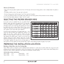
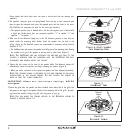
5. Make sure all the RotoLock clamps are in the full clockwise position so that they are
tucked within the mounting hole’s border. Insert the speaker into the hole in the
ceiling (
Figure 6
). The RotoLock system can accommodate a maximum ceiling material
thickness of 1¼”.
• The FastMount tabs will prevent the speaker from falling out of the mounting hole, allowing
the installer to let go of the speaker to pick-up tools or other items (Figure 7).
N
OTE
:T
HE
F
AST
M
OUNT TABS ARE DESIGNED FOR ONE
-
TIME USE ONLY
.I
F THE
SPEAKER IS REMOVED FROM THE MOUNTING HOLE THE
F
AST
M
OUNT TABS WILL
DISCONNECT AND REMAIN INSIDE THE CEILING
.
6. Tighten the four screws on the front of the speaker baffle. The RotoLock clamps will
automatically rotate into position and begin clamping the speaker (
Figure 8
).
• When you notice resistance on the screws the speaker has been clamped successfully.
N
OTE
:T
HE SPEAKER FLANGE IS DESIGNED TO FLEX AND CONFORM TO ANY SMALL
IMPERFECTIONS IN THE CEILING SURFACE
.D
O NOT TIGHTEN THE SCREWS SO
MUCH SO THAT THE FLANGE BOWS
-
OUT
.
IMPORTANT: Always use low-torque settings; NEVER
over-tighten.
7. Attach the grille after the speaker has been installed. Insert about half of the grille into
the groove at the edge of the speaker. Gently fit the remaining half of the grille by work-
ing around the speaker, fitting the grille into the groove as you go.
N
OTE
:Y
OU CAN ADJUST THE TORQUE APPLIED TO THE
R
OTO
L
OCK SCREWS TO
ACHIEVE A PROPER GRILLE FIT
.
RotoLock
®
Clamps
Figure 8:
RotoLock
®
Clamps
FastMount
®
Tabs
Figure 7:
FastMount
®
Tabs
Figure 6: Insert Speaker
Into Mounting Hole