


4
Sensitive source components should be isolated from the Sonamp 1250
MKII with appropriate power conditioning to minimize hum.
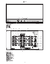
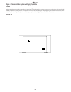
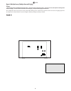
Speaker Connections (page 3 — #5)
Always turn off power and unplug the amplifier before making source
signal or speaker connections.
Use quality speaker wire to assure optimum sound reproduction.
Small gauge or inferior quality wire will degrade imaging, diminish bass
reproduction, and add a generally congested quality to music.
Always check local building codes before installing wire in walls or ceilings.
If connections will be changed frequently, speaker wires may be
terminated with banana or spade ends for convenience. Any connector
should be gold-plated to prevent oxidation, which degrades sound
quality. The 5-way binding posts on the 1250 MKII also accept twisted
bare wire ends through the 45° holes in their center shafts. Tinning the
bare copper wire is recommended. As an option, use contact enhancer
on mating surfaces of connections to retard oxidation and enhance
signal flow. Do not strip more than ½” of the jacket from speaker wires.
Always provide sufficient slack in wires to avoid tension Always contain
any excess wire to prevent tripping hazards.
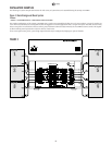
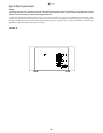
Source Connections (page 3 — #9, #10, #11)
Always use quality high-fidelity interconnect cables such as Sonance
MediaLinQ Silver OFC Interconnects (part # 900843). If source compo-
nents are more than 20 feet from the amplifier, use the LS1 and LR1 bal-
anced line-level sender and receiver to avoid signal degradation.
(Example shown in Figure 6.)
• Connect source components (receiver, preamp, page signal, etc.) to the
Line Inputs (#9) at the top center of the amplifier.
• Connect zone-specific sources (zone output, page signal, video game,
electronic doorbell, etc.) into the Dedicated Channel Inputs (#10).
• Connect additional amplifiers to the non-buffered Line Outputs (#11) at
the bottom center of the amplifier.
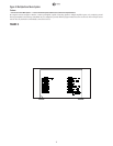
Source Settings (page 3 — #8)
The Sonamp 1250 MKII’s Source Selection DIP switches provide the most
flexible configuration options of any multichannel amplifier. Settings are
changed by setting the switches either ON (left) or OFF (right):
L: Assign output to Line-In LEFT channel source
R: Assign output to Line-In RIGHT channel source
L + R: Mono reproduction of LEFT & RIGHT Line-In sources
AUX: Assign output to Line-In AUX channel source
DIR: Assign output to Dedicated Channel input.
Note: It is possible to assign one or all switches as needed (i.e. L+R+AUX),
where AUX is the page input for a hallway or waiting room with paging.
Volume Controls (page 3 — #7)
The individual channel volume controls allow balancing the desired
sound levels for various zones, or balancing the outputs from right and
left channels to compensate for various room characteristics or seating
arrangements. To prevent tampering place tape over the Volume
Control holes.
Power Trigger Controls
(page 3 — #13, #14, #15)
The Sonamp 1250 MKII may be automatically activated by an input
signal, low voltage trigger, or manual pushbutton. It also provides a 12
volt DC output to trigger other components.
Auto-On Control
(page 3 — #12, #13)
In this mode, the amplifier will automatically turn on when the mini-
mum signal is detected at any of the inputs (Line or Dedicated Channel),
and off after 8 minutes of no input signal. To use the Auto-On feature,
turn the Power switch (page 3, #1) ON and slide the Auto-On switch on
the rear panel (#12) to the ON position.Use the Sensitivity control (#13)
to set the minimum signal level that will activate the amplifier.
AC/DC Input — Voltage Control (page 3 — #14)
Voltage Control activates the amplifier by the presence of current at the
AC/DC Input (#14). Any alternating or direct current from 5 to 24 volts
present at this input will activate the amplifier. Voltage Control is
activated when the Auto-On switch (#12) is set to OFF, the sensitivity
control (#13) is set to Off and the Main Power switch (#1) is turned ON.
If activating the amplifier from a remote point is required, connect a
spare 5 – 24V DC power supply to the AC/DC Input and plug it into a
switched AC outlet or connect it through a switch. Activating the power
supply will turn the amplifier ON.
DC Control Output
(page 3 — #15)
The 12VDC Output terminals provide 200mA of current to trigger another
voltage-controlled component.Any time the amplifier is active (regardless
of how it has been activated), voltage is present at these terminals.
Manual Power On
(page 3 — #1)
If no automatic activation function is required, rotate the Sensitivity
control (#13)) to OFF and move the Auto-On slide switch (#12) to OFF.
The Power switch (#1) will manually activate the amplifier.
Protection Circuitry and Status LEDs (page 3 — #2, #3, #4)
AC On LED (#2): This red LED indicates that the AC power line cord is
plugged-into a live AC outlet. If the main AC line fuse opens, this LED
goes out. The main power switch setting does not impact this LED.
Active LED (#3): This green LED indicates that the amplifier has been
activated via one of the three methods described above.
Protection LEDs (#4): The 1250 MKII has one protection circuit and a
corresponding LED for each pair of channels. These amber LEDs light
during a fault condition. If a channel pair encounters a short-circuit
event, an extremely low impedance, or if its heat sink temperature
exceeds the design maximum, its protection circuit will activate,
disconnecting both channel outputs and activating the corresponding
LED. (All other channel pairs are unaffected.) The affected channel
outputs will automatically re-connect after 2 seconds. If the fault
remains, the channels will disconnect again. This disconnect/reconnect
cycle will continue until the fault is eliminated.
IMPORTANT: Allowing the amplifier to operate with 2 or more
channels in the
disconnect/reconnect
cycle can damage the amplifier.
If a pair of channels are in Bridged mode (see below), the protection
circuitry will sense a short circuit across both positive speaker terminals
in addition to shorts across the positive and negative speaker terminals.
Each time the amplifier is initially plugged in and the Power switch is
turned on, all channel outputs are disconnected for approximately 5
seconds and all 6 protection LEDs will light while the amp’s circuitry is
stabilizing. This prevents spikes and thumps from getting to speakers.
IMPORTANT: Any time the protection circuits are triggered, turn the
Power
switch OFF before troubleshooting.
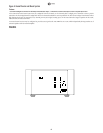
Bridging Channels (page 3 — #5 , #6)
The 1250 MKII’s twelve 50-watt channels can be bridged in pairs, yield-
ing a maximum of six 100-watt channels.
To bridge a pair of channels, move the Bridged/Normal toggle switch
(#6) to the Bridged position. This links the odd-numbered channel
adjacent to the switch with the even-numbered channel directly below it
(channels 1 & 2, channels 3 & 4, etc.). When two channels are bridged
the Source Selection DIP switches (#8) for the odd-numbered channel
function; the switches for the even-numbered channel are disabled.
To connect a speaker to a bridged channel, use the positive (red ‘+’)
terminals of both channels. Connect the speaker’s ‘+’ wire to the odd-
numbered channel’s ‘+’ terminal; connect the speaker’s ‘–’ wire to the
even-numbered channel’s ‘+’ terminal.
IMPORTANT: Speakers connected to bridged channels must have a
nominal impedance of 8 ohms or higher.