


2
SONANCE VISUAL PERFORMANCE
®
8” IN-WALL
Before Installation: Retrofit
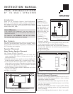
1. Determine the location for the speaker (see
Speaker Placement
on page 1).
2. Perform an obstruction survey to be certain that there are no
studs, conduit, pipes, heating ducts, pocket doors or air returns
in the wall cavity that will interfere with the speaker.
3. All Visual Performance 8” in-wall speakers require a mounting
cutout that is 8
7
/
16” (214mm) wide by 14½” (368mm) high with at
least 3
5
/
8” (92mm) of depth within the mounting cavity.
4. Position the included cutout template where the speaker is to
be located and pencil an outline on the wall.
• If you are unsure about obstructions, drill a small hole in the
center of the outline and insert a coat hanger wire into the
hole to feel-around for possible obstructions.
5. Cut the mounting hole using a keyhole or drywall saw, and
run the speaker wires from the mounting hole to the amplifier
location.
• Consult local building codes before running speaker wires
through walls.
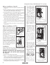
Before Installation: IR Plug
Sonance Visual Performance Series
in-wall speakers have a plug for
installing an IR receiver into the
speaker’s front baffle (see
Figure 4
).
In systems where the electronics are
placed in an inconvenient location
this allows remote controls to be
aimed at the front of the room instead
of at the electronics.
The IR plug is in the form of a bolt
and retaining nut. To remove the
plug, unscrew the nut (located behind
the baffle, see
Figure 5
) and remove
the bolt. The hole is designed to
receive a Sonance OptiLinQ
®
SMR1
or SMR1P Surface-Mount IR receiver.
Insert the IR receiver through the
front of the speaker baffle and use
the nut included with the receiver to
secure it to the baffle.
Installation
Sonance Visual Performance Series speakers feature exclusive
FastMount
®
tabs and an integral RotoLock
®
mounting system for
quick mounting directly into existing walls.
WARNING: THE EDGES OF THE FASTMOUNT TABS
ARE VERY SHARP. USE CAUTION WHEN HANDLING
THE SPEAKER.
1. Remove the paint plug from the speaker.
2. Strip ¼” – ½” of insulation from each speaker lead. Twist the
strands or tin the exposed wire with solder to ensure that there
are no stray strands. (Stray strands that touch each other can
cause a short-circuit that can damage the amplifier.)
3. The speaker’s connector posts are spring-loaded. Push the top
of each connector post down to open the connector and insert
the exposed wires into the holes in the posts.
• The speaker’s positive
post is labeled with a
red dot; the negative
post is labeled with a
black dot. Double-
check that you connect-
ed amplifier “+” to
speaker “+” and ampli-
fier “–” to speaker “–”.
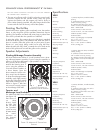
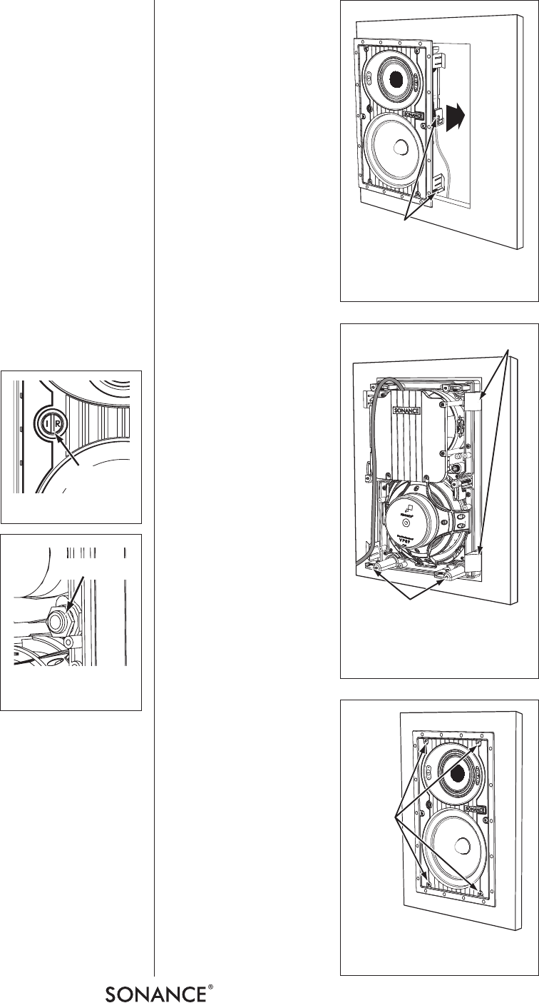
4. Make sure all the
RotoLock clamps are
retracted so that they
are tucked within the
mounting hole’s border.
Insert the speaker into
the hole in the wall
(
Figure 6
). The RotoLock
system can accommo-
date a maximum wall
material thickness of
1¼”.
• The FastMount tabs will
prevent the speaker
from falling out of the
mounting hole, allow-
ing you to let go of the
speaker to pick-up
tools or other items
(
Figure 7
).
NOTE: THE FASTMOUNT
TABS ARE DESIGNED FOR
ONE-TIME USE ONLY. IF
THE SPEAKER IS REMOVED
FROM THE MOUNTING
HOLE THE FASTMOUNT
TABS WILL DISCONNECT
AND REMAIN INSIDE THE
WALL.
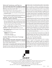
5. Tighten the four screws
on the front of the speaker
baffle. The RotoLock
clamps will automatically
rotate into position and
begin clamping the
speaker (
Figure 8
).
• When you notice resist-
ance on the screws the
speaker has been
clamped successfully.
IMPORTANT:
Always use low-
torque settings;
NEVER over-tighten.
NOTE: ADJUSTING THE
TENSION OF THE
ROTOLOCK CLAMPS SO
THAT THE SPEAKER FRAME
IS FLAT WILL HELP ENSURE
RotoLock Clamps
(retracted)
FIGURE 6: INSERTING THE SPEAKER
INTO THE
MOUNTING HOLE
FastMount Tabs
RotoLock Clamps
(retracted)
FIGURE 7: FASTMOUNT TABS AND
ROTOLOCK CLAMPS
RotoLock
Screws
FIGURE 8: TIGHTENING THE
R
OTOLOCK SCREWS
FIGURE 4: IR PLUG
FIGURE 5: IR PLUG
RETAINING NUT
IR Plug
Retaining Nut