


2
PREPARING THE INSTALLATION LOCATION
All Sonance speakers are designed to be relatively insensitive to
variations in enclosure volume. To achieve the ultimate performance
from your speakers, a section of the ceiling bay can be sectioned-off to
form a back box. Building such an enclosure will create a dramatic
improvement in bass performance and power handling.
Ideal back box volume requirements:
Quintette 522
QR 0.75 ft
3
Quintette 521
QR 0.60 ft
3
Insulating the Ceiling Cavity
To reduce sound transmission to adjacent rooms and further improve
speaker performance, insulate the ceiling cavity by inserting a sheet of
unfaced fiberglass insulation above and below the speaker.
To reduce noise produced by unsupported drywall, install fiberglass
insulation in the ceiling bays adjacent to the speaker location.
INSTALLING THE SPEAKERS
New Construction
For installations in new construction, Sonance recommends using
a Quintette FlexBracket (part#91966) to reserve a location for the
speaker. The FlexBracket is nailed or screwed to the studs and serves as
a guide for the drywaller so that the speaker hole will be in the desired
location once the drywall is installed.
Quintette FlexBrackets are compatible with the RotoLock® mounting
system (see Retrofit, below).
Retrofit
Quintette speakers feature an integral RotoLock® mounting system for
quick mounting directly into existing ceilings and walls. Once the hole is
cut and the cable is run, you can install the speaker in a matter of seconds.
1. Determine the location for the speaker (see Speaker Placement).
2. Perform an obstruction survey to be certain that there are no studs,
conduit, pipes, heating ducts or air returns that will interfere with the
speaker.
3. The cutout for all Quintette In-Ceiling Speakers is 6
7
/8” (175mm).
There also must be at least 3½” (89mm) depth within the ceiling
cavity for the speaker.
4. Find the cutout template provided in the speaker packaging. Position
the template where the speaker is to be located and pencil an outline
on the ceiling.
• If you are unsure about obstructions, drill a small hole in the center
of the outline and insert a coat hanger wire into the hole to
feel-around for possible obstructions.
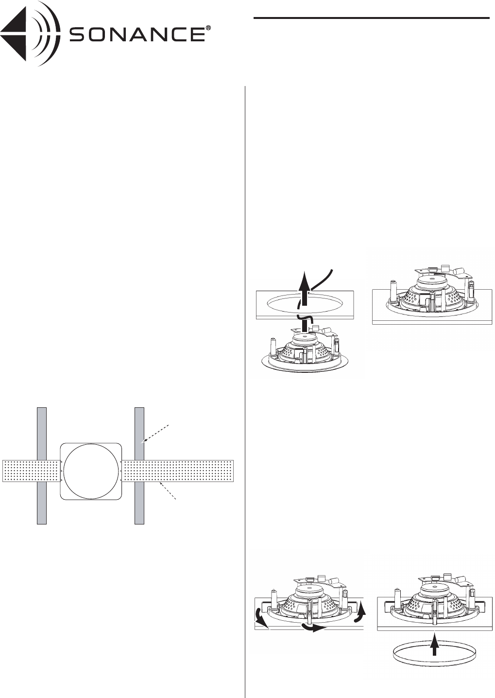
5. Cut the hole using a drywall saw, and run the speaker wires.
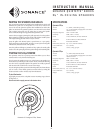
6. Remove the paint plug from the speaker. Connect the speaker wire to
the terminals on the back of the speaker. Double-check that you
connected amplifier + to speaker + and amplifier – to speaker –.
7. Make sure all the RotoLock clamps are in the full clockwise position
so that they are tucked within the cutout border. Insert the speaker
into the hole in the ceiling.
Note: The RotoLock system can accommodate a maximum ceiling
material thickness of 1¼” (32mm).
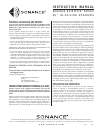
8. Tighten the four screws on the front of the speaker baffle. The
RotoLock clamps will automatically rotate into position and begin
clamping the speaker.
• When you notice resistance on the four screws the speaker has been
clamped successfully.
The speaker flange is designed to flex and conform to any small
imperfections in the wall surface. Do not tighten the screws so much
so that the flange bows-out.
Important: Always use low-torque settings — NEVER over-tighten.
9. Attach the grille after the speaker has been installed. Insert about half
of the grille into the groove at the edge of the speaker. Gently fit the
remaining half of the grille by working around the speaker, fitting the
grille into the groove as you go.
Note: You can adjust the torque applied to the RotoLock screws to
achieve a proper grille fit.
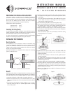
Ceiling Joist
FlexBracket Wing
Illustration 2: Quintette FlexBracket Installation
INSTRUCTION MANUAL
SONANCE QUINTETTE
®
SERIES
5¼” IN-CEILING SPEAKERS
Steps 6 & 7:
Step 8:
Step 9: