


PREPARING THE INSTALLATION LOCATION
All Sonance speakers are designed to be relatively insensitive to
variations in enclosure volume. To achieve the ultimate performance from
your speakers, a section of the ceiling bay can be sectioned-off to form a back
box. Building such an enclosure will create a dramatic improvement in your
speakers’ bass performance and power handling.
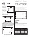
Ideal back box volume requirements:
Insulating the Wall Cavity
You can reduce sound transmission to adjacent rooms and further improve
speaker performance by inserting a sheet of unfaced fiberglass insulation over
the back of the speaker.
To reduce noise produced by unsupported drywall, install fiberglass
insulation in the stud bays adjacent to the speaker location.
Optional Virtuoso Retrofit Enclosures
For installations where it isn’t possible to section-off the stud bay to form a
back box (such as when you’re retrofitting the speakers into an existing
wall), you can effectively reduce sound transmission into adjacent rooms by
fitting the speakers with optional Virtuoso Retrofit Enclosures (part# 92242).
This enclosure is designed specifically to be used with Virtuoso D speakers,
and will noticeably reduce sound “spillover” from the rears of the speakers
into adjacent rooms and spaces.
INSTALLING THE SPEAKERS
Before Installation: New Construction
For installations in new construction, Sonance recommends using
a Virtuoso FlexBracket (part# 92246) to reserve a location for the speaker.
The FlexBracket is nailed or screwed to the studs and serves as a guide for the
drywaller so that the speaker hole will be in the desired location once the
drywall is installed.
Before Installation: Retrofit
1. Determine the location for the speaker (see Speaker Placement on page 1).
2. Perform an obstruction survey to be certain that there are no studs,conduit,
pipes, heating ducts or air returns that will interfere with the speaker.
3. The cutout for all Virtuoso D-series speakers is 8
7
/
16” (214mm) wide and
14½” (368mm) high. There also must be at least 3
7
/8” (99mm) depth
within the wall for the speaker.
4. Position the included cutout template where the speaker is to be located and
pencil an outline on the wall.
• If you are unsure about obstructions, drill a small hole in the center of the
outline and insert a coat hanger wire into the hole to feel-around for
possible obstructions.
5. Cut the hole using a drywall saw, and run the speaker wires.
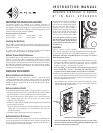
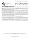
Before Installation: IR Knockout
All Sonance Virtuoso D-series speakers have a knockout for installing an IR
receiver into the speaker’s front baffle. This remote controls to be aimed at the
front of the room instead of at the electronics, in systems where the electron-
ics may be placed in an inconvenient location.
The knockout is in the form of a bolt and
retaining nut. To remove the knockout,
unscrew the nut (located behind the baf-
fle) and remove the bolt. The hole is
designed to receive a Sonance SMR1 or
SMR1P Surface-Mount IR receiver. Insert
the IR receiver through the front of the
speaker baffle and use the nut included
with the receiver to fasten it to the baffle.
Note: The speaker’s grille may reduce
the effectiveness of the IR receiver. If
this occurs, slightly enlarge the holes
in the grille that are directly in front of
the IR receiver.
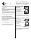
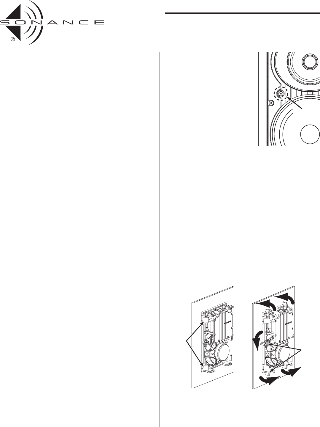
Installation
Sonance Virtuoso D-series speakers
feature exclusive FastMount® tabs and an integral RotoLock® mounting system
for quick mounting directly into existing walls (see Illustration 8, on page 4).
WARNING: The edges of FastMount tabs are very sharp. Use caution
when handling the speaker.
1. Remove the paint plug from the speaker. Connect the speaker wire to the
terminals on the speaker. (The V834
D
has two sets of “+”and “–” terminals
(see below). You can use either set.) Double-check that you connected
amplifier + to speaker + and amplifier – to speaker –.
Note: The V834
D
can be bi-wired by removing the jumpers between
the LF and MF/HF “+” and “–” terminals, and connecting two sets
of speaker wires from the amplifier, one to each set of terminals.
2. Make sure all the RotoLock clamps are in the full clockwise position so that
they are tucked within the mounting hole’s border. Insert the speaker into
the hole in the ceiling. The RotoLock system can accommodate a maxi-
mum wall material thickness of 1¼”.
• The FastMount tabs will prevent the speaker from falling out of the
mounting hole, allowing the installer to let go of the speaker to pick-up
tools or other items (see Illustration 8).
Note: The FastMount tabs are designed for one-time use only. If the
speaker is removed from the mounting hole the FastMount tabs will
disconnect and remain inside the wall.
3
INSTRUCTION MANUAL
SONANCE VIRTUOSO
®
D-SERIES
8” IN-WALL SPEAKERS
FastMount
Tabs
RotoLoc
k
Clamps
Illustration 8: Virtuoso D Installation
Virtuoso V834D: 2.5 ft
3
Virtuoso V833
D: 2.2 ft
3
Virtuoso V832D: 2.0 ft
3
Virtuoso V831
D: 2.0 ft
3
Illustration 6: IR Knockout
IR
Knockout