


8
SIR-PNR1 Installation Guide
SIR-PNR1SIR-PNR1
PIONEER COMPATIBLE
SIRIUS SATELLITE RADIO TUNER
IP BUS
A
B
CD
1
3
2
4
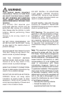
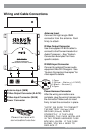
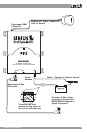
Wiring and Cable Connections
Antenna Input
Connect the right-angle SMB
connector from the antenna. Push
firmly to attach.
IP-Bus Output Connector
Use the supplied IP-BUS cable to
connect to the Pioneer Headunit or
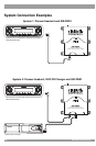
Audio Processor – See “System
Connection Examples” for more
specific details.
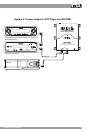
IP-BUS Input Connector
Connect to optional Pioneer audio
equipment like CD Changers - See
“System Connection Examples” for
more specific details.
Antenna Input (SMB)
IP-Bus Output Connector (BLACK)
IP-Bus Input Connector (BLUE)
Power Connector
B
C
D
A
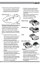
Power Harness Connector
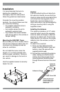
After the wiring connections are
complete, plug the wiring harness into
the connector. Make sure to insert
firmly to lock the connector in place.
*NOTE* BE SURE TO CONNECT
THE BATTERY (Yellow) AND
GROUND (Black) WIRES
CORRECTLY. IF THEY ARE
CROSSED, THE FUSE INSTALLED
IN THE POWER HARNESS FUSE
BOX WILL BLOW. IF THE FUSE
BLOWS, YOU WILL NEED TO
REPLACE IT.
FILTE R &
FUSE B OX
IN
OUT
1 Open
2 Yellow -- Battery (+12VDC)
3 Black -- Ground (-)
4 Open
Power harness with
serviceable fuse box