


MOON Aurora Multi-Channel Power Amplifier
Rear Panel Layout
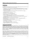
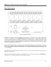
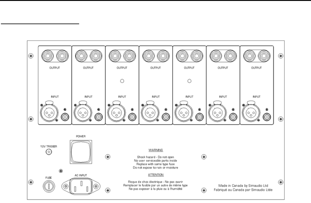
Figure 1: MOON Aurora Rear panel
Regardless of the number of channels your amplifier has, the rear panel will look similar to Figure 1 (above). Depending on
the number of channels built into your MOON Aurora Multi-Channel power amplifier, a corresponding number of input
connectors and output connectors are located on the back panel. If your amplifier has, for example, five channels, then the
two extra sets of connectors for the non-existing 6th and 7th channels are replaced by factory-inserted hole plugs. Should
you wish us to upgrade your amplifier by adding extra channels, we will remove the plugs and install the necessary
connectors to accommodate the extra channels.
Each channel has a balanced input on an XLR connector and a single-ended (unbalanced) input on RCA connector. There is no
switch to toggle from balanced mode to single-ended mode. You may operate the amplifier in either mode, but only one mode
at one time for each channel. Above each of these inputs is a pair of heavy duty gold-plated speaker binding posts (“-” and
“+”) for each speaker.
On the bottom left you will find; The power “main switch” (“0”=off, “1”=on); The “AC Fuse” socket cover; and the “AC in” IEC
receptacle for the power cord.
Directly to the left of the power “main switch” is a “12V trigger” input on a 1/8” mini-jack. This allows for the MOON Aurora
to be turned “on” or “off” using a hard wired remote connected to this input.
____________________________________________________________________________________
Rear Panel Layout 5