


9
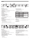
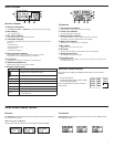
Transmitter RF Power
Reference the following table for setting RF Power:
RF Power Setting System Range Application
1 mW 33 m (100 ft.)
For increased chan-
nel reuse at close
distances
10 mW 100 m (330 ft.) Typical setups
20 mW >100 m (330 ft.)
For hostile RF environ-
ments or long-distance
applications
Note: Using the 20 mW setting decreases the transmitter battery runtime
and reduces the number of compatible systems.
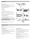
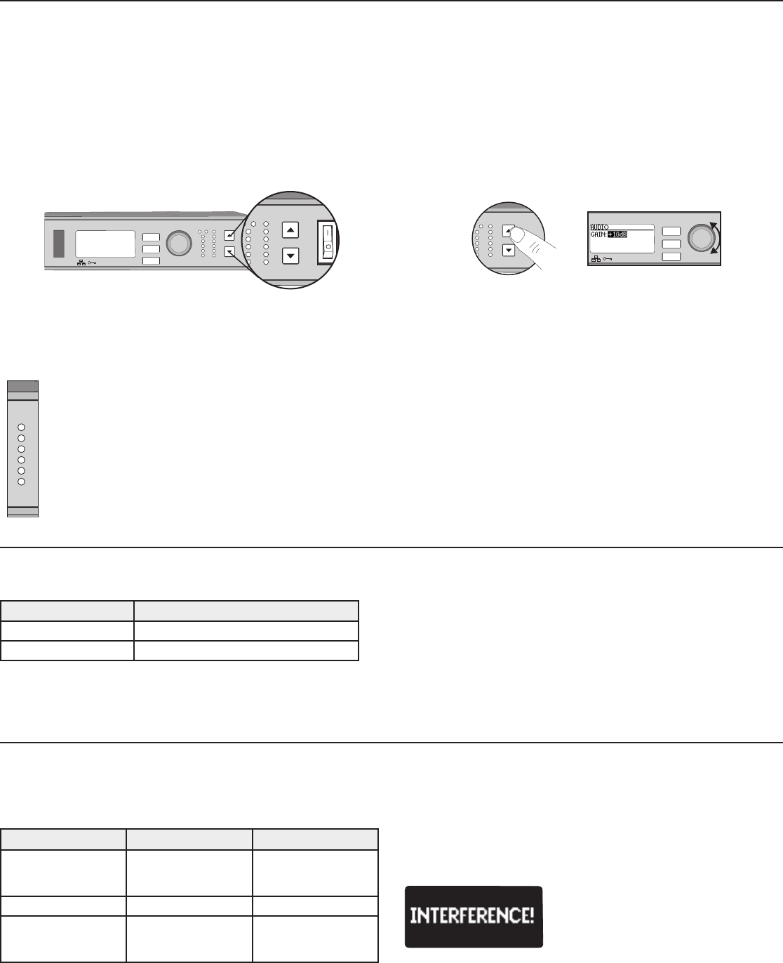
Interference Detection
Interference Detection monitors the RF environment for potential sources of
interference which can cause audio dropouts.
When interference is identified, the RF LEDs illuminate red and the following
warning displays on the receiver LCD panel.
RF
ULXD4Q
Digital Wireless Receiver
push
control
ENTER
EXIT
SCAN
RF
A B
OL
OL
gain power
audio
IR
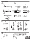
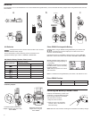
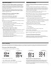
Setting Gain
Adjust gain at the receiver so that the average signal levels are solid green and yellow with peaks that occasionally trigger the red overload LED. Attenuate
the gain if the signal overloads repeatedly.
Set the XLR output to line-level when possible to optimize sound system noise performance.
ULXD4Q
Digital Wireless Receiver
push
control
ENTER
EXIT
SCAN
RF
A B
OL
OL
gain poweraudio
IR
RF
AB
L
OL
gain poweraudio
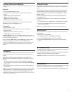
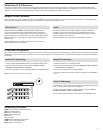
Adjusting Gain
Pressthe▲▼gain buttons on the front of the
receiver to incrementally adjust gain from -18 to +42
dB.
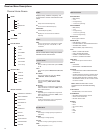
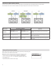
Large Gain Adjustments
RF
A B
OL
OL
gainaudio
ULXD4
Digital Wireless Receiver
sync
push
control
ENTER
EXIT
SCAN
OL
Press and hold a
gain button
or
Use the control wheel in
the
AUDIO menu
Receiver Output Level
The following table describes the typical total system gain from the audio input to the receiver outputs:
Output Jack System Gain (gain control = 0dB)
XLR (line setting) +24 dB
XLR (mic setting) -6 dB*
System Gain Control
The gain control on the receiver sets the audio signal level for the entire system. This allows adjustments to be made during a live performance. It is not
necessary to change the gain on the transmitter (mic offset) to optimize the gain structure. Any required changes to gain should be made from the receiver.
Mute
To mute the audio, use Shure Wireless Workbench
®
software or a third-
party control device.
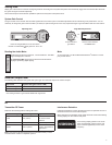
Reading the Audio Meter
If the warning display persists or the audio
drops out repeatedly, perform a Scan and
Sync at the first opportunity to find a clear
frequency.
Audio peaks illuminate the LEDs for 1 second hold time. The RMS
signal is displayed in real time.
OL (Overload) LED: Illuminates red when the internal limiter is
engaged, preventing digital clipping.
*This setting matches a typical wired SM58 audio signal level.