


4
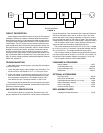
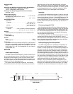
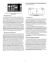
BLOCK DIAGRAM
FIGURE 6
CIRCUIT DESCRIPTION
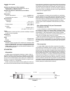
A block diagram of the SM81 is shown in Figure 6. The capacitor
cartridge is followed by a switch-controlled capacitive attenuator
stage which provides for 10 dB attenuation at the cartridge output.
The signal is fed to a field-effect transistor (FET) impedance con-
version stage. The FET output drives an active low-frequency re-
sponse (high-pass) filter controlled by a three-position switch. The
filter output from a compound transistor, Class A, emitter-follower
amplifier is transformer-coupled, providing a balanced output to
the RFI protection filter at the microphone connector. An active,
constant-current power supply circuit regulates the phantom volt-
age, allowing the SM81 to operate over a very wide range of volt-
ages. A reverse voltage protection diode guards against miswired
cables and equipment.
TROUBLESHOOTING
If the SM81 fails to operate properly, verify that the microphone
is powered properly.
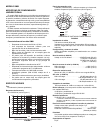
1. Check the power supply output voltage to the microphone. For
the Shure PS1A, this should be 21.5 + 1.5 Vdc open circuit.
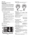
2. Check the voltage on microphone connector pins 2 and 3 (at
back of connector; cable connector disassembled from shell
but connected to microphone). The voltage at pins 2 and 3
with reference to pin 1 should be between 11 and 52 Vdc.
Due to its high packing density and circuit complexity, disassem-
bly of the SM81 is not recommended. Contact Shure's Service De-
partment if problems persist.
ARCHITECTS' SPECIFICATION
The microphone shall be a condenser microphone with a fre-
quency response of 20 to 20,000 Hz. It shall have a unidirectional
pickup characteristic, with cancellation at the sides of 6 dB and a
minimum cancellation at the rear of 15 dB at 1 kHz. The micro-
phone shall have a rated output impedance of 150 Ω for connec-
tion to microphone inputs of 150 ohms or higher. The open circuit
voltage shall be -65 dB (0.56 mV) (0 dB equals 1 volt per microbar).
The microphone shall contain a three-position low-freq-uency
response switch and a lockable 10 dB attenuator pad.
The overall dimensions shall be 212 mm (8-11/32 in.) in length
by 23.5 mm (15/16 in.) in diameter. The handle diameter shall be
20.1 mm (25/32 in.). The weight shall be 230 grams (8oz).
The microphone shall be capable of being powered by a phan-
tom power supply with an output of 11 to 52 Vdc, or by a mixer, au-
dio console or tape recorder capable of supplying 11 to 52 Vdc.
The microphone shall be a Shure Model SM81.
FURNISHED ACCESSORIES
Swivel Adapter........................................................A57F
10 dB Attenuator Lock .......................................34A830
Carrying/Storage Case .....................................65A1797
Windscreen..........................................................49A111
OPTIONAL ACCESSORIES
Pop-Filter Grille...................................................... A81G
Heavy-Duty Windscreen..................................... A81WS
Tripod Microphone Stand (4.3 m [14 ft])..................S15A
Stereo Microphone Adapter ...................................A27M
Cable (7.6m [25ft]) ..................................................C25F
Phantom Power Supply ......................................... PS1A
REPLACEMENT PARTS
Cartridge and Grille Assembly ............................... R104
CAPACITOR
CARTRIDGE
FET IMPEDANCE
CONVERTER
LF RESPONSE
FILTER
CLASS A
COMPOUND
AMPLIFIER
RFI
FILTER
BALANCED
TRANSFORMER
REGULATOR/
REVERSE
VOLTAGE
PROTECT
CAPACITIVE
ATTENUATOR