


1
General Description
The Shure PA411 Antenna Combiner distributes DC power and RF signal
for up to four Shure PSM
®
300 transmitters. The compact half-rack system
significantly reduces the amount of antennas and power supplies needed
when using multiple systems.
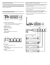
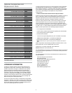
Front and Rear Panels
ྙ ྚ ྛ ྜ
POWER INPUT POWER OUT
RF ANTENNA INPUTS
ྜྷ
ྞ
ྟ
① RF Output Antenna Connector
Use the ¼ wave antenna supplied with the P3T transmitter, or
any other Shure antennas that cover 470-865 MHz
② RF LED Indicators
Green : RF signal present
Red: RF signal overload
③ Power LED
Green : Power on
Green/red flashing: Power output overload
④ Power Switch
⑤ Power Input
Requires a Shure PS45 power supply
⑥ Power Output
Requires a Shure PS411-PC power distribution cable to deliver
power to transmitters
⑦ RF Inputs
Connect to transmitter RF outputs
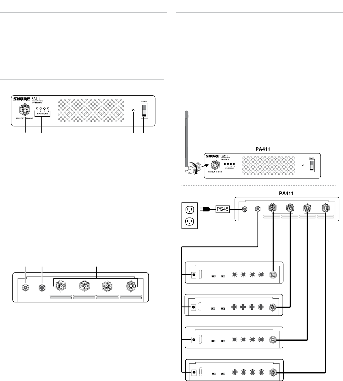
Power and RF Connections
1. Connect the Shure PS45 power supply to a power outlet and to the
power input on the PA411.
2. Connect the 1-to-4 power cable to the DC power output on the PA411.
3. Connect a power terminal from the 1-to-4 power cable to each P3T
transmitter power input.
4. Connect an antenna to the P3T antenna output on the front panel.
Acceptable antennas include the ¼-wave antenna supplied with the P3T
transmitter or any Shure antennas that cover 470-865 MHz.
5. Connect each P3T antenna output to an antenna input on the PA411,
using BNC coaxial cable.
POWER INPUT
POWER OUT
RF ANTENNA INPUTS
P3T
MONO/STEREO-MX LINE/AUX LEFT/CH.1 IN RIGHT/CH.2 INL - LOOP OUT - R ANTENNAPOWER
MONO/STEREO-MX LINE/AUX LEFT/CH.1 IN RIGHT/CH.2 INL - LOOP OUT - R ANTENNAPOWER
MONO/STEREO-MX LINE/AUX
LEFT/CH.1 IN
RIGHT/CH.2 INL - LOOP OUT - R ANTENNAPOWER
MONO/STEREO-MX LINE/AUX LEFT/CH.1 IN RIGHT/CH.2 INL - LOOP OUT - R ANTENNAPOWER