


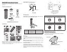
MX400SMP Surface Mount Preamp
Permanent mount for conference tables or lecterns. Includes LED
logic input.
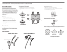
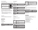
Furnished Accessories
65A2190
Wing Nut
95A2529
5 Pin XLR-F
66A405
Rubber Isolation
Rings
66A11907
Plastic Cap
MX400SMP Surface Mount Kit
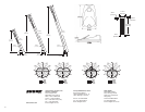
Installation
2.5 cm
(1 in)
1 2 3
4 5 6
Note: Over tightening the wing nut reduces shock isolation.
Caution: To prevent bending pins, line up key with notch and seat
connector fully before twisting to lock.
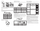
MX400SMP Pin Assignments
42
51
3
Audio −
Audio +
Logic (LED IN)
5-Pin XLR
DIP Switches
Set DIP Switch 1 up to engage the low cut filter, which attenuates
frequencies by 6 dB per octave below 150 Hz.
Switch Down (default) Up
1 Full frequency
response
Low cut filter
2 LED steady LED flashes
LED Logic
To operate the LED indicator, use the included 5-pin XLR con-
nector to wire the microphone to an automatic mixer or other logic
device.
Note: Connect the LED IN to the gate output to illuminate the LED
when the channel is gated on.
Do not use the relay ports on Crestron and AMX devices. Use the
I/O logic ports instead.
The LED logic may not function when connecting to devices
that do not have internal "pull-up resistor" logic circuits, such as
ClearOne DSP products. External pull-up resistor circuits can be
added for each microphone. Visit www.shure.com/FAQ for detailed
instructions.
+5 V
GND
Mic
Device
Logic Port (I/O)
Logic Connection
Connection to device with
internal "pull-up resistor"
logic circuit
MX405, 410, 415
Logic LOW (0 V) Logic HIGH (+5 V)
Green Red
MX405R, 410R, 415R
Logic LOW (0 V) Logic HIGH (+5V)
Red Off/flashing
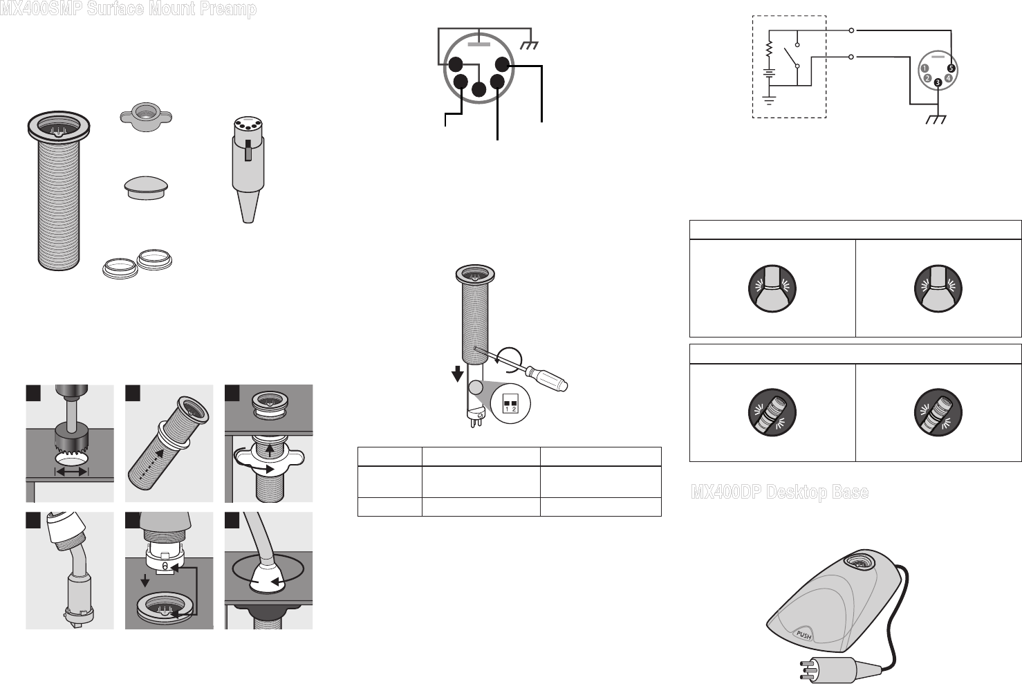
MX400DP Desktop Base
The MX400DP moveable desktop base includes a configurable
mute button with logic output.
Desktop Base
Attached Cable
MX400DP Desktop Base
3