


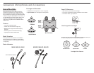
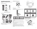
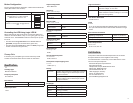
Installation
1 2 3
Caution: To prevent bending pins, line up key with notch and seat
connector fully before twisting to lock.
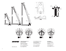
Cable
The 20 ft. attached cable is terminated with a 3-pin XLR connector.
For logic applications, open the XLR connector to access the three
unterminated logic conductors.
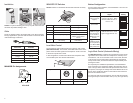
Wire Color Function
Red Audio +
Black Audio−
White SWITCH OUT
Orange LED IN
Green Logic Ground
Shield Mic Common Ground
MX400DB Pin Assignments
Audio −
Audio +
3-Pin XLR
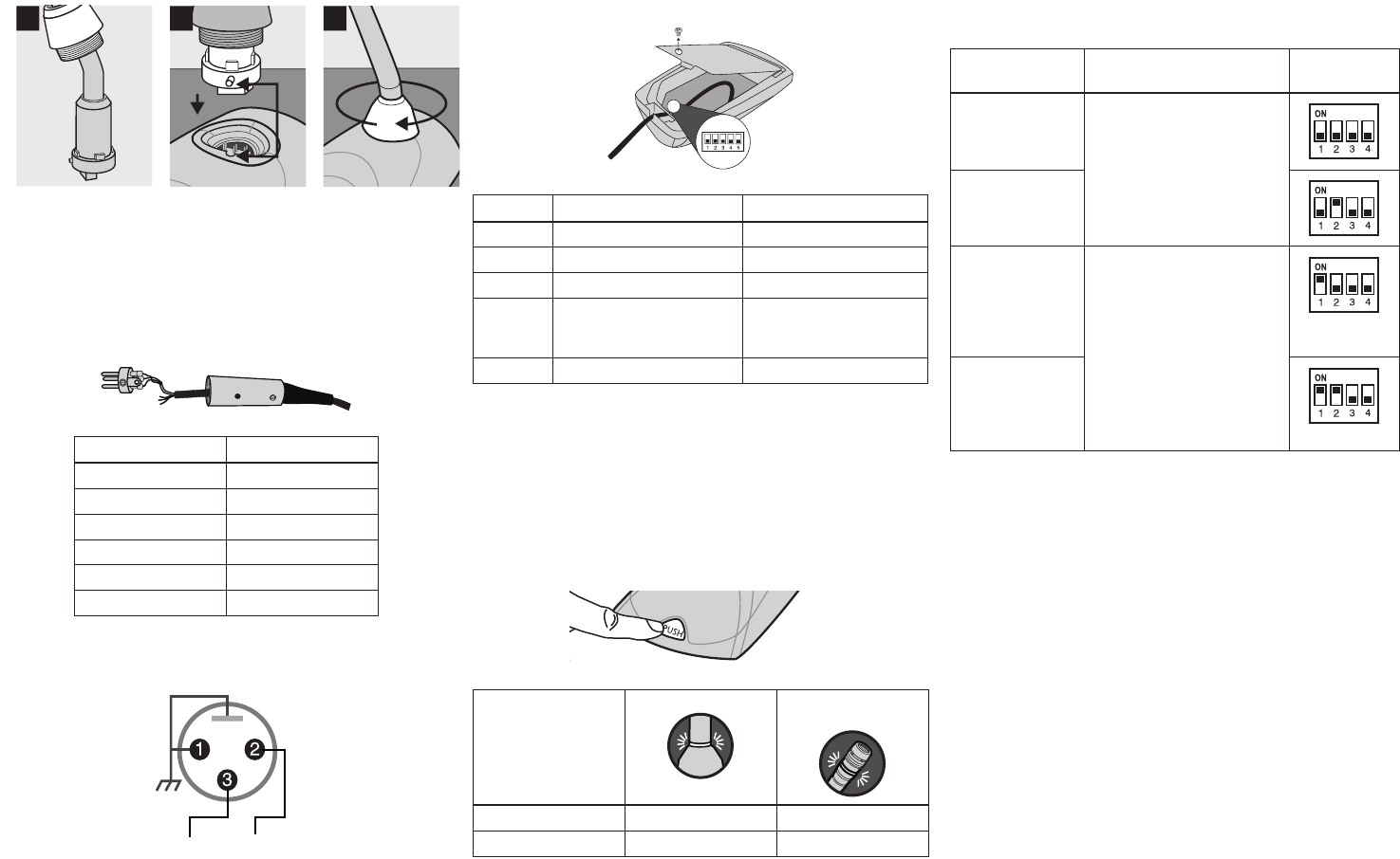
MX400DP DIP Switches
Caution: Failure to reinstall the setscrew will reduce RF immunity.
Switch Down (default) Up
1 Momentary Toggle
2 Push-to-Mute Push-to-Talk
3 Local Mute Logic Control
4 Full Frequency Range Low Cut Filter (attenuates
6dB per octave below
150 Hz)
5 LED Steady LED Flashes
Local Mute Control
The microphone ships configured for local (manual) mute control
(DIP Switch 3 down). In this mode, the PUSH button on the micro-
phone mutes the audio signal at the microphone. Audio is not sent
to the audio outputs when muted.
In this configuration, the LED color reflects the microphone state,
as controlled by the user with the PUSH button.
Microphone Status MX405, 410, 415 MX405R, 410R,
415R
Active Green Red
Muted Red Off/flashing
Button Configuration
For local mute control operation, use DIP Switches 1 and 2 to con-
figure the button behavior.
Button Behavior SWITCH OUT Logic
Signal
DIP Switch
Setting
Momentary:
push-to-mute (as
shipped).
When pushed, SWITCH OUT
(red wire) falls to 0 V. When
released, SWITCH OUT re-
turns to +5 V.
Momentary:
push-to-talk
Toggle: Push and
release to toggle
the microphone
on or off. Mic is
active when pow-
ered on.
Push and release sets
SWITCH OUT to 0 V. Push
again to toggle back to +5 V.
Toggle: Push and
release to toggle
the microphone on
or off. Mic is mute
when powered on
Logic Mute Control (Automatic Mixing)
Set DIP Switch 3 up to configure the microphone for logic control
applications where audio from the microphone is muted by an ex-
ternal device, such as an automatic mixer. In this mode, the local
mute function of the PUSH button is bypassed (the microphone
always sends audio) and the LED does not respond directly from
pushing the button.
As required by the installation specifications, wire the SWITCH
OUT conductor in the microphone cable to the automatic mixer or
other TTL logic device. When the talker presses the button on the
microphone, it changes the voltage level at the SWITCH OUT con-
ductor, which signals the device to mute audio for that channel or
perform some other function.
To control the LED on the microphone, wire the LED IN conductor
to the gate output on the automatic mixer (or any TTL logic device).
4