


2
Dimensions
43 mm x 94 mm x 140 mm (H x W x D)
(1.7” x 3.7” x 5.5”)
Weight (unit only)
0.56 kg
1.24 lbs.
Weight (packaged)
0.86 kg
1.90 lbs.
Certification
Meets FCC Part 15 Class B, Eligible to bear CE mark (see conformance
statement)
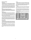
–6
+1
–5
–4
–3
–2
–1
+0
d
B
u
10 100k20 50 100 200 500 1k 2k 5k 10k 20k 50k
Hz
80 Hz
160 Hz
High Pass (Low Cut)
FREQUENCY RESPONSE
Figure 1
MIC INLINE OUT
PHANTOM
48 V
12 V
OFF
BATTERIES
LIMITER POWER
160
80
FLAT
GAIN (dB)
ON ON
0
18
28
36
42
46
50
54
58
62
66
123 4 56
78910
FREQUENCY RESPONSE
Figure 2
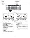
Front Panel Controls and Indicators
1 LIMITER/Peak LED
Bi-color LED illuminates amber to indicate limiter activi-
ty; illuminates red at 3 dB below clipping.
2 LIMITER Switch
Activates the peak limiter. Limits to +17 dBu output.
3 High Pass Filter Switch
Three-position switch inserts an 80 Hz or 160 Hz corner
frequency filter, 6 dB per octave. Center position of
switch removes the filter from the signal path.
4 Rotary GAIN Switch
Selects the amount of gain from input to output, adjust-
able in 11 increments.
5 POWER Switch
Powers the unit when switch is in the up position.
6 POWER LED
Bi-color LED illuminates green when the unit is pow-
ered and changes to red when approximately four
hours of battery life remain.
Back Panel Connectors and Controls
7 Battery Compartment
Requires two AA batteries for operation. Insert positive
(+) end of battery first.
8 LINE OUT
Transformer balanced XLR line-level output. +22 dBu
peak output level.
9 PHANTOM Power Switch
Three-position switch selects either 48-volt or 12-volt
phantom power. Center position turns phantom power
off.
10 MIC IN
Transformer-balanced XLR input accepts microphone
level signals.