


2
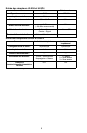
SPECIFICATIONS
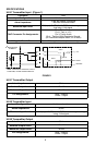
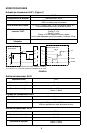
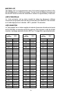
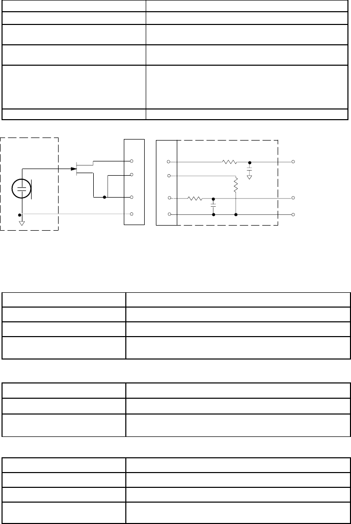
ULX1 Transmitter Input (Figure 1)
Connector: TA4F
Input Configuration: Unbalanced, active
Actual Impedance:
18 kΩ with lavalier microphone
1 MΩ with instrument cable
Maximum Input Level:
10 Vp–p (+10 dBV) for 1% THD at minimum gain set-
ting using 1 kHz signal.
TA4F Connector Pin Assignments:
Pin 1: Tied to Ground
Pin 2: Tied to +5 V
Pin 3: Tied to Audio
Pin 4: Tied thru 20kΩ Resistor to Ground.
(On instrument adapter cable, Pin 4 floats)
Voltage for Remote Power: +5 V supplied to microphone cartridge
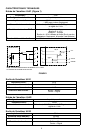
27 pF
20K Ω
27 pF
+5 V
AUDIO
GROUND
ULX1 MIC JACK BOARD
2
1
4
500 Ω
500 Ω
MICROPHONE
ELEMENT
3
2
1
3
4
NOTE: LAVALIER MIC TIES PINS 3 AND 4
TOGETHER; GUITAR CABLE DOES NOT.
FIGURE 1
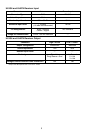
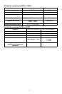
ULX1 Transmitter Output
Actual Impedance: 50 Ω
Nominal Output Level: 20 mW
Maximum Output Level: 30 mW
Pin Assignments: Shell = Ground
Center = Signal
ULX2 Transmitter Input
Input Configuration:
Unbalanced, active
Actual Impedance:
20 kΩ
Maximum Input Level:
10 Vp–p (+12 dBV) for 1% THD at minimum gain setting
using 1 kHz signal.
ULX2 Transmitter Output
Actual Impedance:
50 Ω
Nominal Output Level:
20 mW
Maximum Output Level:
30 mW
Pin Assignments:
Shell = Ground
Center = Signal