


5
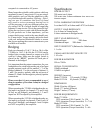
Specifications
POWER OUTPUT
200 watts into 8 ohms.
300 watts into 4 ohms minimum sine wave con-
tinuous output.
TOTAL HARMONIC DISTORTION
Less than 0.05% at 8 ohms and 0.075% at 4 ohms.
OUTPUT LOAD IMPEDANCE
8 or 4 ohms in Normal mode
8 ohms minimum in Bridged mode
INPUT LOAD IMPEDANCE
Balanced input 20K ohms
Unbalanced input 20K ohms.
INPUT SENSITIVITY (Balanced or Unbalanced)
1.1 volts.
UNBALANCED INPUT SENSITIVITY
1.10 volts.
POWER BANDWIDTH
5Hz to 75kHz.
SIGNAL TO NOISE RATIO
100dB wideband
110dB A-weighted.
WEIGHT (in carton)
Model 7/2100A 115 pounds (52.2Kg)
Model 5/5210A 85 pounds (38.6Kg)
DIMENSIONS
Width 19 inches (483mm)
Depth 17.7 inches (450mm)
Height 7 inches (177mm).
POWER REQUIREMENTS
Model 7/2100A:
120V operation (USA/Canada) 2 x 15A
230V operation (Europe/Australia) 2 x 7.5A
Model 5/5210A:
120V operation (USA/Canada) 2 x 12A
230V operation (Europe/Australia) 2 x 6A
receptacle is connected to AC power.
Many homes have double outlet sockets which are
supported by one 15 amp circuit. If you are using 4
ohm speakers, and you like the amplifier to play
very loud through each speaker, (Warning : Expos-
ing your ears to continuous loud levels of sound
may result in serious permanent hearing loss) it
will be necessary to use two different power sup-
ply outlets EACH of which should be supplying
separate 15 amp circuits. This is the reason for sup-
plying the two power cords with different lengths.
If your speakers are 8 ohm impedance, you can
connect both power cords to the same double out-
let 15 amp circuit. You are strongly advised to check
with your authorized Sherbourn dealer to ensure
that you are making the correct connection to your
available wall outlets.
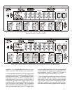
Bridging
Each two channels of 1 & 2, 3 & 4 or 5 & 6 of the
7/2100A (or 1 & 2, 5 & 6 for the 5/5210A) can be
bridged into a mono channel to output up to 400
watts at 8 ohms. Make sure the toggle switch is
placed in the “BRDG” position for each pair of
channels to be bridged.
It is important that the output connections for your
loudspeakers be wired between the pair of red post
speaker outputs (each will be marked “+”) of the
bridged channels. Use the red posts of channel 1,
3 and 5 for positive polarity, and the red posts of
channel 2, 4 and 6 for the negative polarity speaker
connections.
Please note that it is not recommended to use 4
ohm (or speakers of less than 4 ohm) in a bridged
configuration.
When operating the 7/2100A in bridged mode, au-
dio input is accepted via channels 2, 4 and 6 only
(if they are all bridged), and channels 1, 3 and 5
inputs are NOT accepted by the amplifier.
When operating the 5/5210A in bridged mode, au-
dio input is accepted via channels 2 and 6 only (if
they are all bridged), and channels 1 and 5 inputs
are NOT accepted by the amplifier.