


4
Trigger Mode Switch
On
Setting the trigger mode switch to the ON position
allows the 7/2100A or 5/5210A to stay “on” all the
time. The power amplifier can only be turned off
by turning off the front panel switch or by discon-
necting the two power cords.
Music (Automatic Signal Sensing)
Setting the trigger mode switch to the MUSIC po-
sition sets the 7/2100A or 5/5210A into an auto-
on-standby power control mode. The amplifier can
sense a very low-level music signal fed to any of
the signal inputs which will turn the amplifier into
an active state and will play music. When the mu-
sic stops and no further signal is received for more
than 5 to 7 minutes (typically) the amplifier will
turn into a standby mode, which cuts off the power
consumption substantially. The amplifier will wake
up from the standby mode whenever it again re-
ceives a music signal.
Important note for using the 12V trigger: If 12V
DC is not used for triggering, make sure the trig-
ger switch is not set to the 12V position or the
amplifier will not come out of the ‘power-on-
standby’ mode.
12V
Setting the trigger mode switch to 12V allows the
power-on-standby function to be controlled by a
12V DC voltage connected to the 12V input con-
nector. When 12V DC is present at the 12V trigger
input, the amplifier will be turned ON, and when
the 12V disappears it will enter the standby mode
in a few seconds. Under standby mode, no music
signal will go through the amplifier and there is no
output sent to the speakers. The amplifier will wake
up from the standby mode whenever it receives a
12V trigger input again.
Important note for using the LDS Switch: For
every first installation of a 7/2100A or 5/5210A
amplifier, do not set the LDS switch to the OFF
position until the switch has been used to sequen-
tially check through each connection, or the am-
plifier will not output a signal.
Operating the LDS switch
After physically installing the 7/2100A or 5/5210A
amplifier in a location according to the safety in-
structions at the beginning of this manual, care-
fully complete the signal cable wiring and speaker
lead connections.
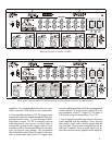
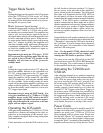
Check and make sure that the LDS switch is set to
the full clockwise direction (position 7). Connect
the two power cords and turn on the amplifier’s
power switch on the front panel. The front panel
blue light will illuminate and the LDS LED (on
the rear panel) will show the status of the speaker
connection at the speaker output terminal of speaker
number 7. If the LED is green, it indicates a good
speaker connection has been made and a correct
speaker impedance has been used. Orange indicates
an open circuit or a speaker of higher impedance
is used. Red indicates either a short circuit con-
nection or a speaker impedance that is too low for
the amplifier.
Sequentially test each speaker connection by wind-
ing the switch in a counterclockwise direction from
7 through to 1 observing the LED color for each of
the 7 positions. If a red or orange color is detected,
check and rewire the connection of that channel
until the LED turns green.
Note – For the model 5/5210A, channels 3 and 4
are not installed and you will see orange when
rotating the LDS Switch to positions 3 and 4.
You must never turn the LDS switch to the OFF
position whenever an LDS LED is RED during the
above checking. This could connect a dead short
to the amplifier which may cause damage.
Activating the 7/2100A and
5/5210A
After checking through every speaker connection
with the LDS switch and having confirmed that all
LDS LEDs are green, then remove the tiny lock-
ing screw between the OFF and 1 position. Turn
the switch to the OFF position which will fully ac-
tivate the 7/2100A or 5/5210A. The power-on-
standby control is then handed over to either the
external 12V DC Trigger, or the Music Trigger, or
the always power ON position (but controlled by
the front panel power switch) depending upon how
the trigger mode setting is made. Make sure to re-
install the locking screw so that the LDS switch
cannot be turned because to do so will immedi-
ately disable the power on setting of the switch.
Power Cords
In order to obviate the need to install a special 20/
30 amp circuit (that will be required if seven 4 ohm
speakers are used) your 7/2100A or 5/210A has
been equipped with two power cords. Please note
that the rear “Master” AC receptacle must be con-
nected to the AC power first in order to allow power
to enter the “Slave” receptacle of the amplifier. The
amplifier will not power up if only the rear “Slave”