


03/12/17 XL-MP130_11-20.fm
11
XL-MP130
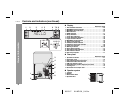
∂ Preparation for Use
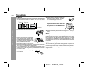
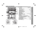
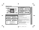
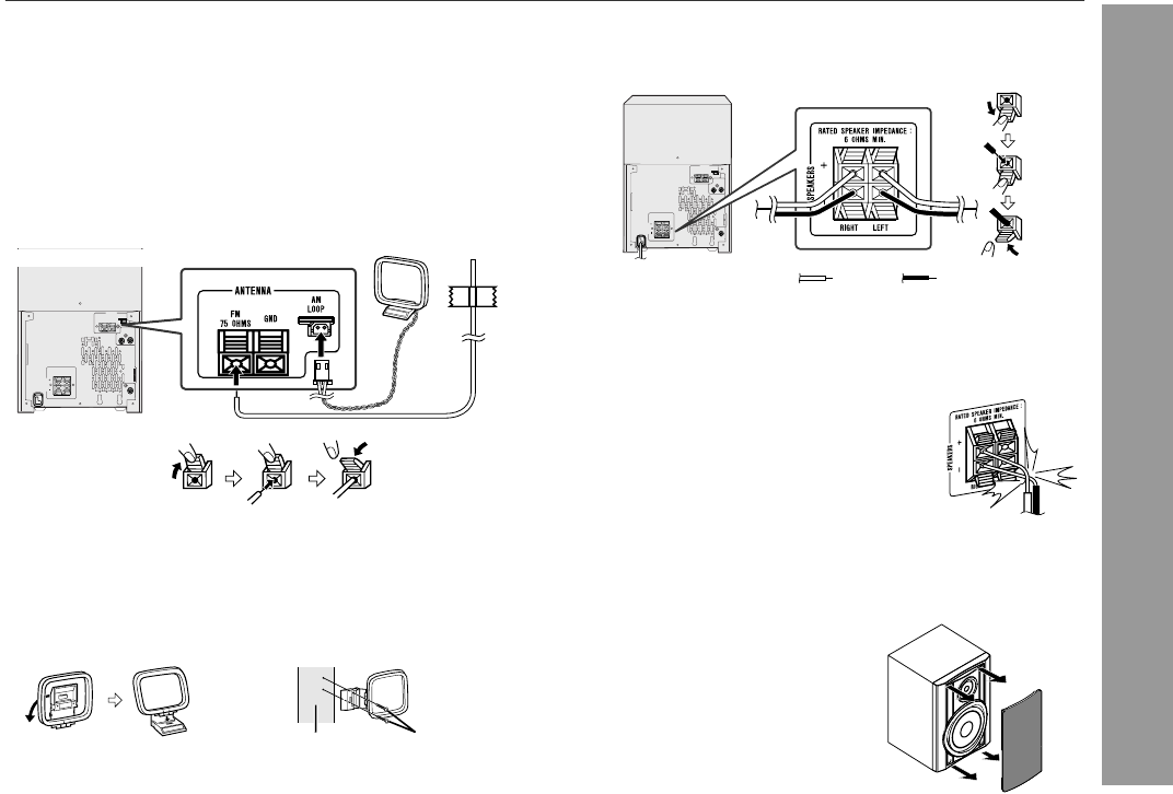
Antenna connection
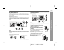
Supplied FM antenna:
Connect the FM antenna wire to the FM 75 OHMS terminal and po-
sition the FM antenna wire in the direction where the strongest signal
can be received.
Supplied AM loop antenna:
Connect the AM loop antenna to the AM LOOP jack. Position the AM
loop antenna for optimum reception. Place the AM loop antenna on
a shelf, etc., or attach it to a stand or a wall with screws (not sup-
plied).
Note:
Placing the antenna on the unit or near the AC power cord may
cause noise pickup. Place the antenna away from the unit for better
reception.
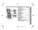
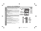
Installing the AM loop antenna:
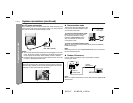
Speaker connection
Connect the black wire to the minus (-) terminal, and the red wire to
the plus (+) terminal.
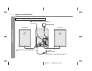
Caution:
Speaker grilles are removable
< Assembling > < Attaching to the wall >
Wall Screws (not supplied)
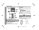
RATED SPEAKER IMPEDANCE:
6 OHMS MIN.
AC INPUT
ANTENNA
RIGHT
RIGHT LEFT
GND
FM
75 OHMS
AM
LOOP
VIDEO/AUX
IN
SUBWOOFER
PRE-OUT
SPEAKERS
LEFT
Use speakers with an impedance of 6 ohms or more, as lower im-
pedance speakers can damage the unit.
Do not mistake the right and the left chan-
nels. The right speaker is the one on the right
side when you face the unit.
Do not let the bare speaker wires touch
each other.
Do not allow any objects to fall into or to be
placed in the bass reflex ducts.
Do not stand or sit on the speakers. You may
be injured.
Incorrect
Make sure nothing comes into contact
with the speaker diaphragm when you
remove the speaker grilles.
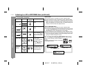
RATED SPEAKER IMPEDANCE:
6 OHMS MIN.
AC INPUT
ANTENNA
RIGHT
RIGHT LEFT
GND
FM
75 OHMS
AM
LOOP
VIDEO/AUX
IN
SUBWOOFER
PRE-OUT
SPEAKERS
LEFT
BlackRed