


11
05/12/2 CD-ES777(U)2.fm
TINSEA095AWZZ
Preparation for Use
CD-ES777
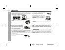
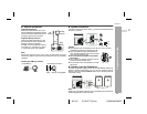
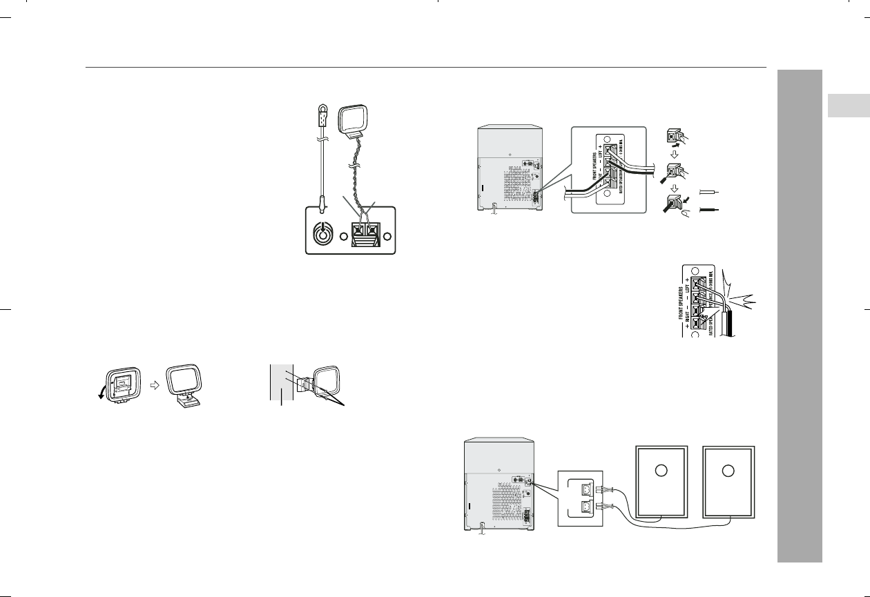
Antenna connection
Note:
Placing the antenna on the unit or near the AC power cord may
cause noise pickup. Place the antenna away from the unit for better
reception.
Installing the AM loop antenna:
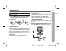
Speaker connection
Connect the black wire to the minus (-) terminal, and the red wire to
the plus (+) terminal.
Caution:
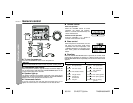
Speaker Light-Up Connection
Connect the speaker light-up wires to the SPEAKERS LIGHT-UP
jacks for speaker illumination. To turn off the speaker light-up
feature, press the CLEAR/DIMMER button on the remote control for
2 seconds or more.
Note:
Placing the right speaker light-up wire to the RIGHT jack and the left
speaker light-up wire to the LEFT jack.
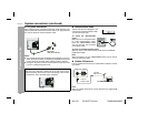
Supplied FM antenna:
Connect the FM antenna wire to the
FM 75 OHMS jack and position the FM
antenna wire in the direction where the
strongest signal can be received.
Supplied AM loop antenna:
Connect the AM loop antenna to the
AM and GND terminals. Position the
AM loop antenna for optimum
reception. Place the AM loop antenna
on
a shelf, etc., or attach it to a stand
or a wall with screws (not supplied).
< Assembling > < Attaching to the wall >
Wall Screws (not supplied)
ANTENNA
FM
75 OHMS
AM
GND
AM loop
antenna
FM
antenna
White
Black
Use speakers with an impedance of 6 ohms or more, as lower
impedance speakers can damage the unit.
Do not mistake the right and the left chan-
nels. The right speaker is the one on the right
side when you face the unit.
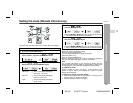
Do not let the bare speaker wires touch
each other.
Do not allow any objects to fall into or to be
placed in the bass reflex ducts.
Do not stand or sit on the speakers. You may
be injured.
Incorrect
AC INPUT
Blac
k
Red
AC INPUT
SPEAKERS
LIGHT-UP
RIGHT
LEFT
LEFT SPEAKER
RIGHT SPEAKER
2