


12
06/1/5 CD-G15000_E2.fm
TINSEA128AWZZ
Preparation for Use
CP-G15000
CD-G15000
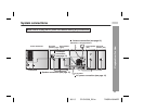
System connections (continued)
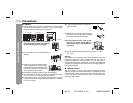
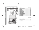
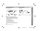
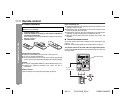
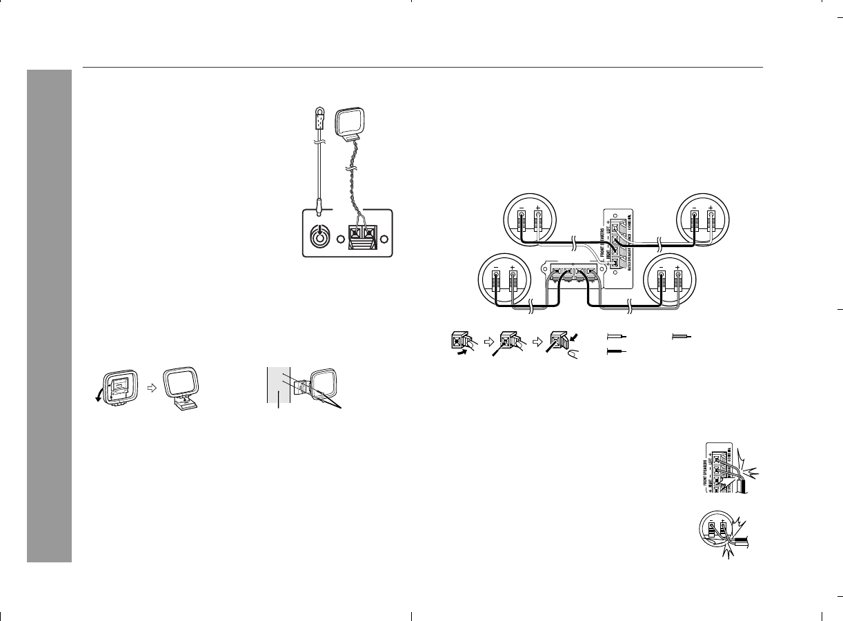
Antenna connection
Note:
Placing the antenna on the unit or near the AC power cord may
cause noise pickup. Place the antenna away from the unit for better
reception.
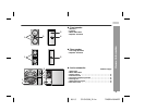
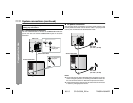
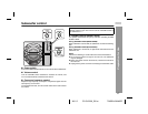
Installing the AM loop antenna:
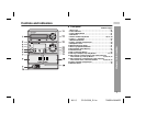
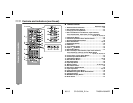
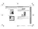
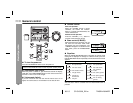
Speaker connection
Front speakers:
Connect the black wire to the FRONT SPEAKERS (-) terminal, and
the red wire to the FRONT SPEAKERS (+) terminal.
Rear speakers:
Connect the black wire to the REAR SPEAKERS (-) terminal, and the
grey wire to the REAR SPEAKERS (+) terminal.
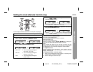
Caution:
Supplied FM antenna:
Connect the FM antenna wire to the
FM 75 OHMS jack and position the FM
antenna wire in the direction where the
strongest signal can be received.
Supplied AM loop antenna:
Connect the AM loop antenna to the
AM and GND terminals. Position the
AM loop antenna for optimum
reception. Place the AM loop antenna
on
a shelf, etc., or attach it to a stand
or a wall with screws (not supplied).
< Assembling > < Attaching to the wall >
Wall Screws (not supplied)
ANTENNA
FM
75 OHMS
AM
GND
AM loop
antenna
FM
antenna
Connect the speaker wires to the speakers first, then to the unit.
Never mistake the FRONT SPEAKERS and the REAR
SPEAKERS terminals. Otherwise the unit or the speakers may be
damaged.
If you use other speakers with impedance lower
than that specified, the unit may be damaged.
Front speakers: 8 ohms Rear speakers: 16 ohms
Do not mistake the right and the left channels. The
right speaker is the one on the right side when you
face the unit.
Do not let the bare speaker wires touch each
other.
Do not allow any objects to fall into or to be placed
in the bass reflex ducts.
Do not stand or sit on the speakers. You may be in-
jured.
RIGHT
RATED SPEAKER IMPEDANCE : 16 OHMS MIN.
LEFT
REAR SPEAKERS
Black
Red
Front speaker (right)
Rear speaker (right) Rear speaker (left)
Front speaker (left)
Grey
Incorrect
Incorrect