


13
ᕡᕢᕣᕤ ᕥ ᕦ ᕨᕧ ¸Ƹ¹ƹ Ƽƺƽµᕩ
12
ƻ
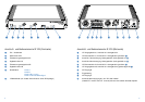
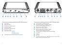
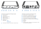
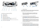
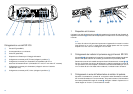
Connections and operating elements of the SI 1015 (front panel)
ᕡ ON/OFF switch
ᕢ LED power indicator
ᕣ Overmodulation indicator channel A
ᕤ Level control channel A
ᕥ Overmodulation indicator channel B
ᕦ Level control channel B
ᕧ Channel selector switch: channel A
channel B
channel A/B, 2 x mono
channel A and B, stereo
ᕨ IR transmitting diodes (for direct monitoring via an IR receiver)
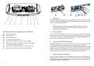
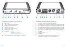
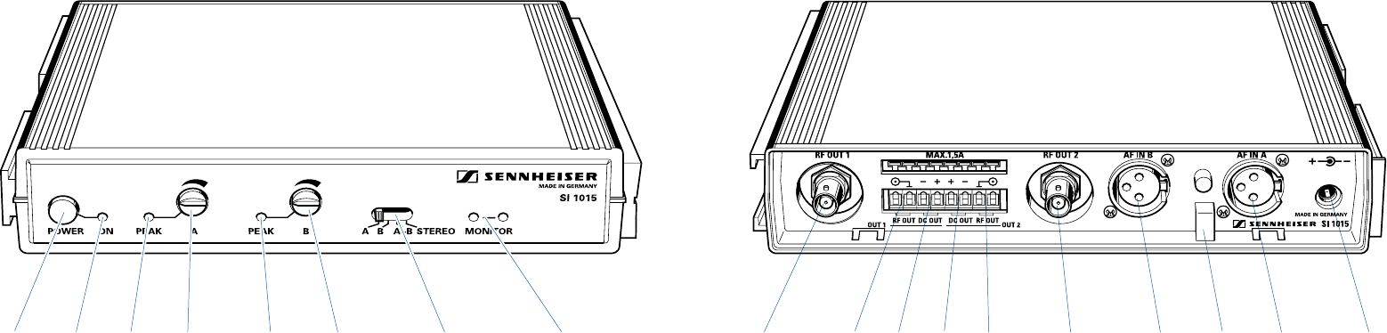
Connections and operating elements of the SI 1015 (back panel)
ᕩ RF output socket 1 for connecting a radiator
µ Barrier strip RF contacts 1 for connecting a radiator
(alternative connection to ᕩ, wired in parallel)
¸ Barrier strip DC outputs for radiator 1
¹ Barrier strip DC outputs for radiator 2
Ƹ Barrier strip RF contacts 2 for connecting a radiator
(alternative connection to ƹ, wired in parallel)
ƹ RF output socket 2 for connecting a radiator (same signal as ᕩ)
ƺ AF input B
ƻ Cable grip
Ƽ AF input A
ƽ Input socket for plug-in mains unit – power supply, 25 - 35 V DC via NT 1015
plug-in mains unit or via a different DC source.