Operation
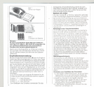
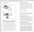
Insertion 01the batteries and battery test.
Fig 1
Operating the battery
compartment
Fig.2
Insertion 01the batteries.
N.B.:
Only alkaline-manganese batteries 01the type 1.5 V
"Miero" IEC LR 03 inay be used, sinee perfeet
operation 01the transmitter is only guaranteed with
these.
After the batteries have been inserted, switch 2 is
set at position "On" with the aid lor the enclosed
switching implement or some other switching tool.
The battenes are correctly Inserted II the red operat-
ing display 3 illuminates. The LED serves simul-
taneously as a battery contral display. The display
go es out il the battery voltage drops below 2.4 V.
The RF output power remains constant down to
approx. 1.5 V. To avoid any unwelcome surprises
the transmitter should be switched on lor around
10min. after the insertion 01new batteries and the
control display observed. II the LED goes out during
this time, one 01the batteries is delective.
7
1
J
Sensitivity adjustment
The sensitlvity 01the microphone input can be adjusted
up to the level 01the expected sound levels In8 stages
with the sensitivity control 4 This adJustment should
be carried out in conJunction with areceiver which has a
sWing display. such as EM 1036 for example. The
sensitivlty IScorrectly adjusted when approx. 30 %
swing display (apprax 20 dB AF-Ievel modulation
reserve) is reached at the level peaks. Dunng adjust-
ment the mike should be held or flxed In the position
In wh Ich it is latergoing to be used. Good results will be
achleved with the sensltivity control set to the
lollowing positions:
Position 1, 2 = loud voices
Position 3 = normal voices
Position 4 - 8= low voices
Foroperating the switch the switching tool supplied
has to be used. Inorder to ensure that the tool
stays with the transmitter afterthe adjustment has
been carried out itshould be snapped onto the
microphone cable.
1
J
Operation with limiter
II the switch 5 is set at position " a high quallty limiting
ampliller is activated. enabling distortion-Iree trans-
mission even ifthe level-control reserve ISconsiderably
exceeded This possibllity of controlling the amplili-
catlon should however only be used when the
sensltlvity control positions 6 - 8 have to be worked
with and when wldely dlftering sound levels are
expected
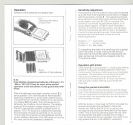
Fixing the pocket transmitter
The transmitter's minimal dimensions and tlat design
mean Itcan easlly be stored In ajacket ortrouser pocket.
The unit ISprevented from falling out by means of a film
clip wlth wh ich the transmitter mayaiso be attached
to the waistband or bel!.
With the button-in linen bag GZT 2012 included the
pocket transmitter may be lixed to costumes,
hosiery ect. Belore the SK 2012 is pushed into
the bag the clip should be removed trom the trans-
mitter. This is done by bending apart the clip. After
the transmitter has been pushed into the bag it
must be lixed with the two gussets. Two slots in the
bag enable the clip to be refitted il necessary.
8


