


ENG
2019
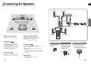
CONNECTIONS
Example: Digital signal components such as a Set-Top Box or CD Recorder.
Analog signal components such as a VCR or TV.
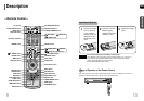
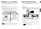
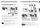
Connecting an External Digital / Analog Component
Connecting External Components
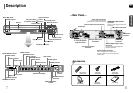
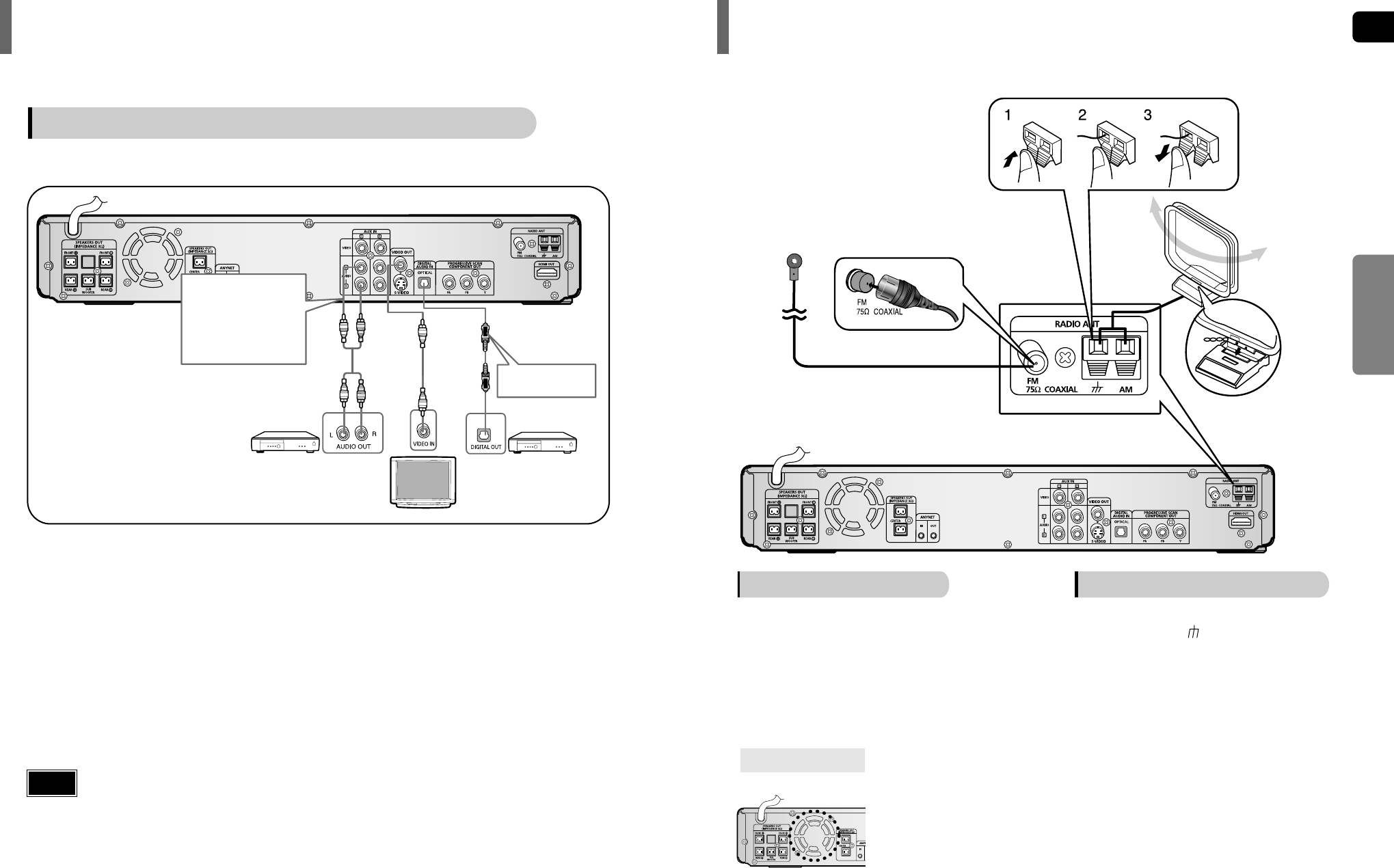
Connecting the FM and AM Antennas
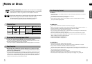
The cooling fan supplies cool air to the unit to prevent overheating.
Please observe the following cautions for your safety.
•
Make sure the unit is well-ventilated. If the unit has poor ventilation, the temperature inside the unit could rise
and may damage it.
•
Do not obstruct the cooling fan or ventilation holes. (If the cooling fan or ventilation holes are covered with a
newspaper or cloth, heat may build up inside the unit and fire may result.)
Cooling Fan
FM antenna connection AM antenna connection
1. Connect the FM antenna supplied to the FM
75Ω COAXIAL terminal.
2. Slowly move the antenna wire around until
you find a location where reception is good,
then fasten it to a wall or other rigid surface.
1. Connect the AM loop antenna supplied
to the AM and terminals.
2. If reception is poor, connect an outdoor
single vinyl-covered wire to the AM
terminal. (Keep the AM loop antenna
connected).
Snap the tabs on the loop into
the slots of the base to
assemble the AM loop antenna.
FM Antenna (supplied)
AM Loop Antenna
(supplied)
If AM reception is poor, connect an
outdoor AM antenna(not supplied).
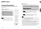
Press AUX on the remote control to select ‘DIGITAL IN / AUX1 / AUX 2’.
• Each time the button is pressed, the selection changes as follows: DIGITAL IN ➝ AUX 1 ➝ AUX 2.
• You can also use the FUNCTION button on the main unit.
The mode switches as follows: DVD/CD ➝ DIGITAL IN ➝ AUX1 ➝ AUX2 ➝ FM ➝ AM.
Connect the Digital Input (OPTICAL) to the Digital Output on the external digital component.
2
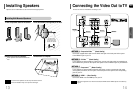
Connect Video Out on the Home Theater to Video In on the TV.
1
4
Connect Audio In on the Home Theater to Audio Out on the external analog component.
• Be sure to match connector colors.
3
• If you have connected an external digital component and also an Analog component to Video In (1, 2) at
the same time, there will be video from AUX 1 even when you select DIGITAL IN.
• If you have connected Audio In (L, R) to 1, connect Video In to 1 as well, and if you have connected
Audio In (L, R) to 2, connect Video In to 2 also.
• When you select Aux 1 or 2, you are selecting Video 1 or 2 inputs respectively.
Note
Optical Cable
(not supplied)
Audio Cable
If the external analog
component has only one
Audio Out, connect either
left or right.
External Digital
Component
External Analog
Component