


Alignment and Adjustments
1-3Samsung Electronics
(GND)
VTVM
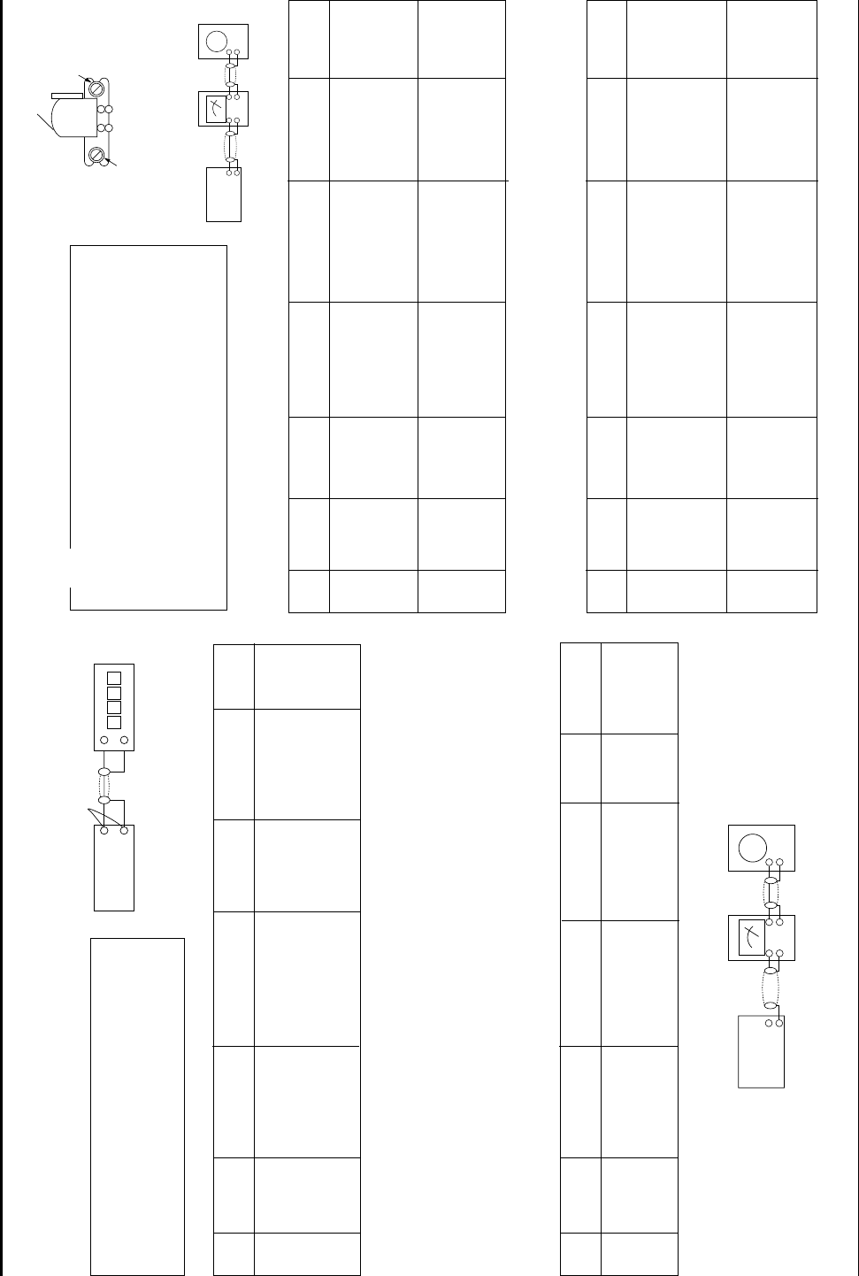
1-2-1 To Adjust Tape Speed
1) Measuring tape: i) MTT-111 (or equivalent)
(Tapes recorded with 3kHz)
ii) MTT-5512 (or equivalent)
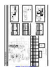
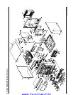
2) Connect the cassette deck to the frequency counter
as in figure 1-4.
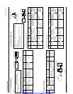
1) Before the actual adjustment, clean the play/recording
head.
2) Measuring tape :
i) MTT-114(or equivalent 10kHz AZIMUTH control)
ii) MTT-112(or equivalent) :
3) The cassette deck is connections as shown in figure 1-6.
Notes
Notes
NOR
SPEED
Control
1
OUT
(connected
to the frequency
counter)
Turn USR1 to
left and right
3KHz
Remark
Standard
To Adjust
Pre-Setup
Item
Step
Pre-Setup
Condition
1) Deck 1:MTT-111
2) Press PLAY
SW button
3) Deck 2:MTT-5512
AZIMUTH
1
2
SPK OUT
(VTVM is
connected to
the scope)
1) Turn the control
screw to as shown
in Figure 1-5.
Max output
and same phase
(both channels)
After
adjustment
secure it with
REGION
LOCK.
Adjust to level
and same as
R-CH.
L-CH:Turn JSR2L
to the right and
left
R-CH : fixed.
See the
diagram for
adjustment
locations.
Remark
Standard
To Adjust
Pre-Setup
Item
Step
Pre-Setup
Condition
Same as
above
After putting MTT-
114 into Deck 1
1)Press PLAY button.
PLAY MTT-112
on Deck 1.
PlayBack
out Level
AZIMUTH
1
2
SPK OUT
(VTVM is
connected to
the scope)
1) Turn the control
screw to as shown
in Figure 1-5.
Max output
and same phase
(both channels)
After
adjustment
secure it with
REGION
LOCK.
Check level
and same as
Deck1 level
No Adjustment
See the
diagram for
adjustment
locations.
Remark
Standard
To Adjust
Pre-Setup
Item
Step
Pre-Setup
Condition
Same as
above
After putting MTT-
114 into Deck 2
1)Press PLAY button.
PLAY MTT-150
on Deck 2.
PlayBack
out Level
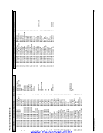
1-2-2 To Adjust PlayBack Level
@ Adjust Deck 2 Play Level
! Adjust Deck 1 Play Level
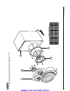
Cassette Deck
output
SPK OUT
Frequency Counter
Figure 1-4
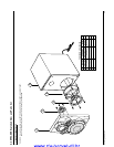
Figure 1-5
SPK OUT
Recording /Play head
AZIMUTH control screw
Figure 1-6
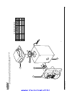
In Out
SET
Oscilloscope
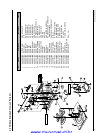
1-2 Cassette Deck
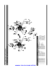
REC
Bias
Voltage
1
Connect to
DCW2 as in
Fig.1-7 and read
the VTVM.
L-CH;DSR2
and R-CH;DSR1
to the right and
left.
6V
Remark
Standard
To Adjust
Pre-Setup
Item
Step
Pre-Setup
Condition
Input MTT-5512
into Deck2,then
press REC button.
See diagram
for adjustment
location
Adjust REC Bias Voltage
Figure 1-7
SET
Oscilloscope
VTVM
IN
JCW3
www.rtv-horvat-dj.hr