


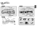
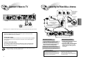
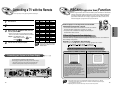
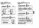
Connect Video to TV
11 12
CONNECTIONS
Composite Video (Good Quality)
Connect the supplied video cable from the VIDEO OUT jack on the back panel of the
system to the VIDEO IN jack on your television.
S-Video (Better Quality)
If you television is equipped with an S-Video input, connect an S-Video cable (not supplied)
from the S-VIDEO OUT jack on the back panel of the system to the S-VIDEO IN jack on
your television.
Component Video (Best Quality)
If your television is equipped with Component Video inputs, connect a component video
cable (not supplied) from the Pr, Pb and Y jacks on the back panel of the system to the
corresponding jacks on your television.
Composite
Video
Component
Video
S-Video
TV
•
When the Progressive scan mode is selected, the VIDEO and S-VIDEO outputs do not feed
any signals. See page 16 to select Progressive Scan.
*
Depending on your TV, Component Video input connectors may be marked as DVD Video input connectors.
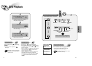
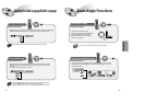
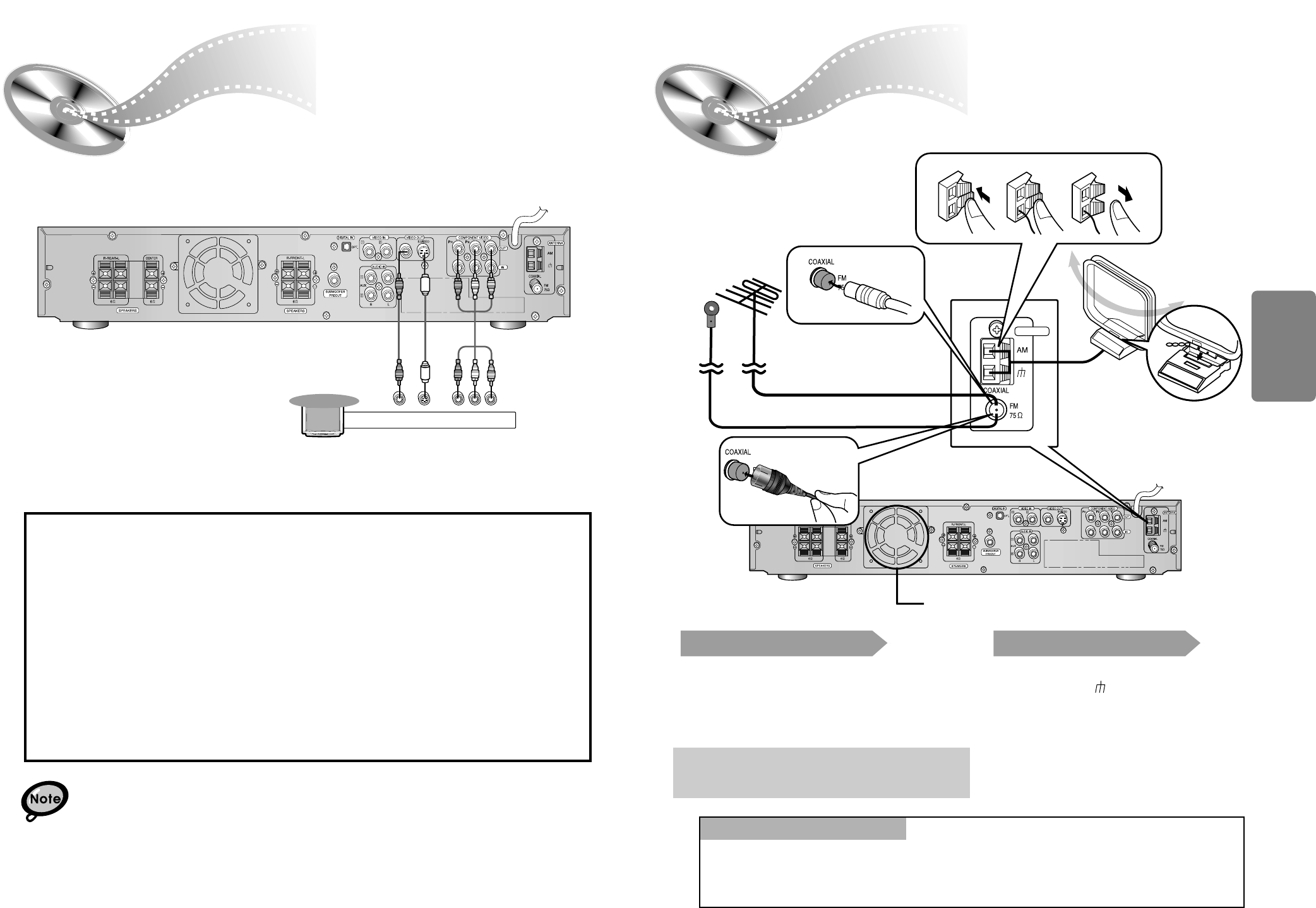
FM antenna connection
1. Connect the FM antenna supplied to the FM 75Ω
COAXIAL terminal as temporary measure.
2. Slowly move the antenna wire around until you
find a location where reception is good, then
fasten it to a wall or other rigid surface.
•
If reception is poor, connect an outdoor antenna.
Before attaching a 75Ω coaxial cable (with a standard
type connector), disconnect the supplied FM antenna.
AM
(MW) antenna connection
1. Connect the AM loop antenna supplied
to the AM and terminals.
2. If reception is poor, connect an outdoor
single vinyl-covered wire to the AM
terminal. (Keep the AM loop antenna
connected).
Connecting the FM and AM
(
MW
)
Antennas
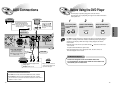
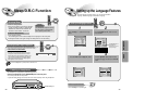
A cooling fan is mounted on the rear panel of the center unit to
prevent abnormal temperature inside the center unit, thus assuring
normal operation. The cooling fan automatically starts rotating to
supply external cool air to the inside of the center unit when the
internal temperature exceeds the specified limit.
For safety, observe the following carefully.
• Make sure there is good ventilation around the center unit. Poor
ventilation could overheat and cause damage.
• DO NOT block the cooling fan and the ventilation openings or
holes. (If they are blocked by a newspaper or cloth, etc., the heat
may not be able to escape.)
Snap the tabs on the loop into the
slots of the base to assemble the
AM loop antenna.
Cooling fan (See “About Cooling Fan” below.)
ANTENNA
123
If FM reception is poor,
connect an outdoor FM antenna
(not supplied).
FM Antenna (supplied)
AM Loop Antenna
(supplied)
If AM reception is
poor, connect an
outdoor AM
antenna(not
supplied).
(About the cooling fan)