


4
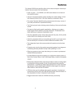
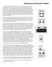
Guided Tour - VX3500 Front Panel
o
Hartke Systems
Transient Attack
POWER
MODEL 3500 350 WATTS
INPUT PRE AMP CONTOUR MASTER
0
3
5
10
15
-18
3
5
10
15
+18
0
3
5
10
15
-18
3
5
10
15
+18
LOW PASS
HIGH PASS
5
4
3
2
1
0
6
7
8
9
10
VOLUME
PASSIVE
COMPRESSION
5
4
3
2
1
0
6
7
8
9
∞
5
4
3
2
1
0
6
7
8
9
10
5
4
3
2
1
0
6
7
8
9
10
+15
+12
+9
+6
+3
+2
0
-2
-3
-6
-9
-12
-15
+15
0
-15
8KHz
5KHz3KHz2KHz1KHz500Hz250Hz125Hz64Hz30Hz
8KHz
5KHz3KHz2KHz1KHz500Hz250Hz125Hz64Hz30Hz
GRAPHIC EQUALIZER
IN
OUT
A B
TUBE SOLID STATE
ACTIVE
1
3
2
456
78
9
10
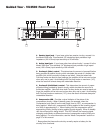
1. Passive Input jack - If your bass guitar has passive circuitry, connect it to
the Model 3500 here. This standard 1/4” unbalanced jack provides a high
impedance (100 k Ohms) input sensitivity of 20 millivolts.
2. Active Input jack - If your bass guitar has active circuitry,* connect it to the
Model 3500 here. This standard 1/4” unbalanced jack provides a high imped-
ance (100 k Ohms) input sensitivity of 60 millivolts.
3. Pre-Amp A (Tube) control - This determines the amount of preamplification
being provided by special circuitry which simulates the sound of a classic tube
amplifier (this circuitry actually includes a real tube!). Note that when both
Pre-Amp knobs are used at equal settings, the amplifier will be twice as loud as
when only one is used. Avoid setting both Pre-Amp knobs on maximum (“10”),
since the result will almost always be undesirable distortion.
4. Pre-Amp B (Solid State) control - This determines the amount of pream-
plification being provided by special circuitry which simulates the sound of a
solid state amplifier. Note that when both Pre-Amp knobs are used at equal set-
tings, the amplifier will be twice as loud as when only one is used. Avoid setting
both Pre-Amp knobs on maximum (“10”), since the result will almost always be
undesirable distortion.
5. Compression LED - Provides a visual indicator of the status of the
compression circuitry. When lit steadily green (for example, when the
Compression knob [see #6 on the next page] is set to “Off”), no compression is
being applied. When unlit, compression is being applied to the incoming signal
at a ratio of approximately 2:1. When flashing red, the compression ratio is
approaching infinity (limiting is being applied to peak signals). When lit steadily
red, the entire signal is being limited. This LED “follows” the incoming signal,
changing continuously as different amounts of compression and/or limiting are
being applied. For more information, see the “About Compression” section on
page 15 of this manual.
* Bass guitars that have active circuitry normally require a battery for the
circuitry to be functional.