


5
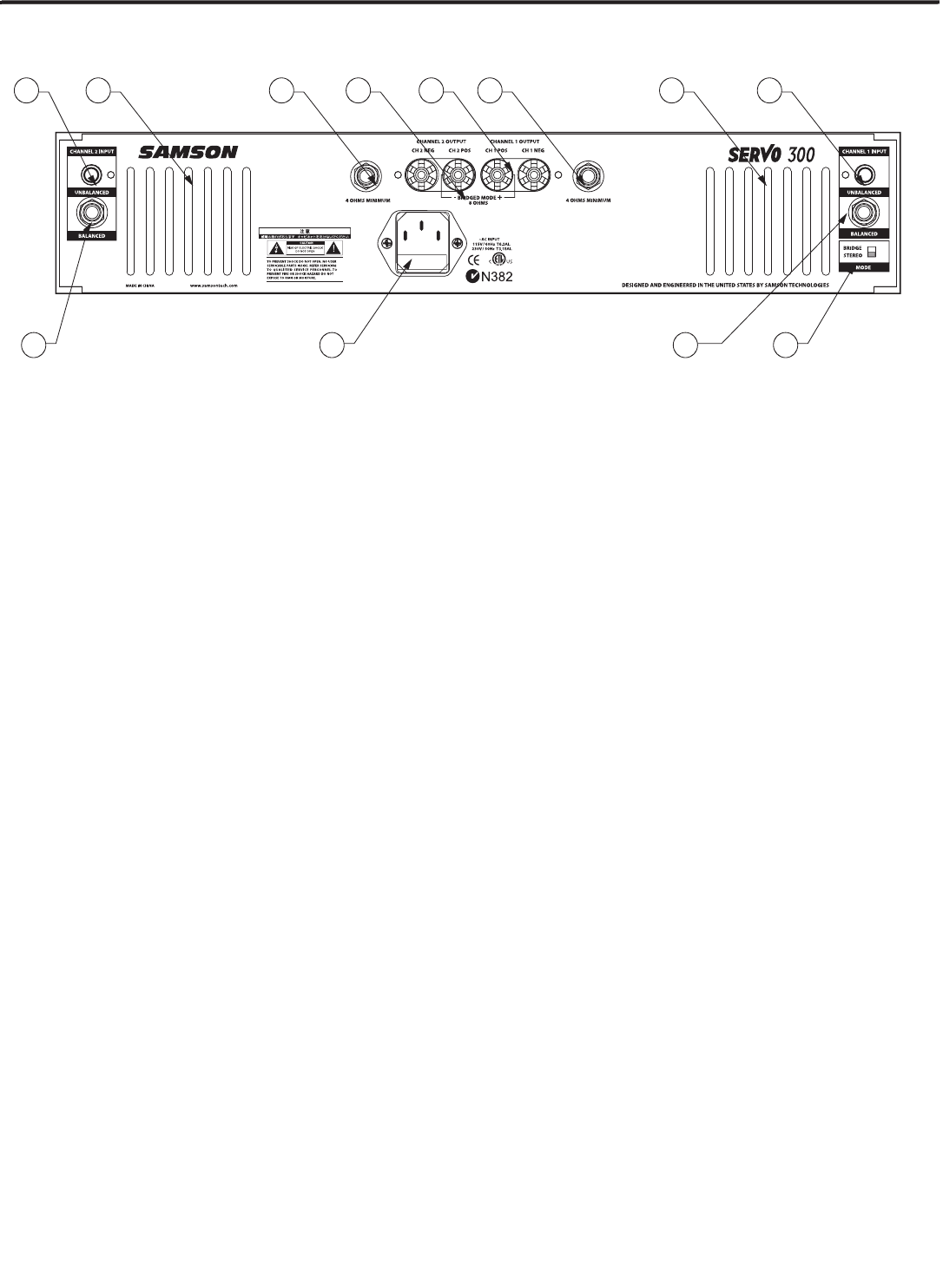
Guided Tour - Rear Panel
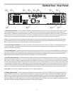
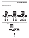
1: RCA Input connectors
– You can connect unbalanced incoming signals to the Servo series using the RCA connectors, which
are wired as follows: Pin 2 (or Tip) hot, and Pin 1 (or Sleeve) ground. The Servo Series accepts input levels of any strength but
needs at least -10dBV dBu to achieve maximum power. Stereo signals should be connected to both the Channel 1 and Channel
2 input jacks; however, when operating the Servo Series in Bridged mode, use the Channel 1 input jack only. See page 8 in this
manual for more information about Bridge mode and page 9 in this manual for full interconnection instructions.
2: Fan
- This variable-speed fan provides vital cooling to your Servo Series (the hotter the amp gets, the faster the fan blows!).
Make sure that both the front and rear panels are kept free of all obstructions and that cool, fresh air is accessible at all times.
Also, try to ensure that the Servo Series is used in a dust-free environment.
3: 1/4-inch Output Connectors
- Use these to connect each channel of the Servo Series to, 4-ohm or 8-ohm loudspeakers with
1/4-inch input jacks. See page 8 in this manual for more information about Bridged mode and page 9 in this manual for full
speaker connection instructions.
4: 5-way Binding Post
- Use these to connect each channel of the Servo Series to 4-ohm or 8-ohm loudspeakers. Be sure to con-
nect the loudspeaker correctly, with the red (+) terminal normally connected to the positive input of the speaker and the black
(ground) terminal normally connected to the negative input of the speaker. See page 8 in this manual for more information
about Bridge mode and page 9 in this manual for full speaker connection instructions
5: 1/4-inch Input Connectors
- Connect incoming signals to these electronically balanced inputs, using the 1/4” TRS (Tip/Ring/
Sleeve) plugs, wired as follows: Pin 2 (or Tip) hot, Pin 3 (or Ring) cold, and Pin 1 (or Sleeve) ground. We recommend the use of bal-
anced three-conductor cabling wherever possible (unbalanced two-conductor 1/4” plugs can also be inserted into these inputs,
but you’ll get better signal quality and less outside noise and hum if you use balanced lines). The Servo Series accepts input levels
of any strength but needs at least +4 dBu to achieve maximum power. Stereo signals should be connected to both the Channel
1 and Channel 2 input jacks; however, when operating the Servo Series in Bridged mode, use the Channel 1 input jack only. See
page 8 in this manual for more information about Bridge mode and page 9 in this manual for full interconnection instructions.
6: AC input
- Connect the supplied heavy-gauge 3-pin “IEC” power cable here.
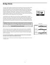
7: Bridge / Stereo switch
- For normal operation, place this two-way switch in its lower (“STEREO”) position. When placed in its
upper (“BRIDGE”) position, the signal arriving at the Channel 1 input only is again routed to both power amplifiers (again, the
Channel 2 input is ignored), but the two power amplifiers are bridged together. For more information, see the “Bridge Mode”
section on page 8 in this manual and the “Servo Series Connections” section on page 9 in this manual. WARNING: Due to the
extremely high power output of the Servo Series when used in Bridge mode, be sure to use only loudspeakers sufficiently rated to
handle the resultant wattage (in Bridge mode, these must be 8-ohm speakers).