


6
Setting Up and Using Your Servo Series
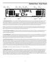
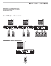
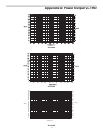
Bridge / Stereo switch
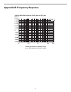
Output connectors
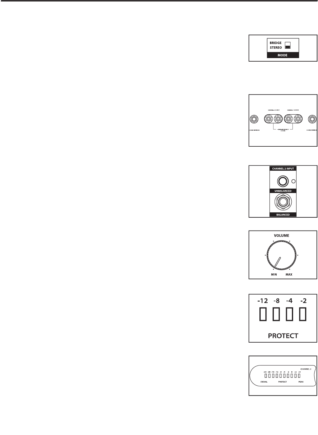
Input connectors
Protection LED
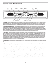
Channel Input control
Three-segment LED meter
Setting up your Servo Series is a simple procedure which takes only a few minutes:
1. Remove all packing materials (save them in case of need for future service) and decide where the
amplifier is to be physically placed—it can be used free-standing or mounted in a standard 19” rack,
requiring only two rack spaces. When installed, make sure that both the front and rear panels are
unobstructed and that there is good ventilation around the entire unit (we recommend the use of
spacer panels, especially if multiple amplifiers are used in a rack.)
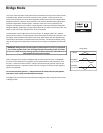
2. Set the rear panel Bridge/ Stereo switch as desired (see the “Bridge Mode” section on page 8 in this
manual for more information).
3. Make the speaker connections, using the banana or 1/4-inch output connectors on the rear panel.
It is never a good idea to power up any amplifier that is not connected to loudspeakers. When oper-
ating in Stereo mode, any loudspeakers with a minimum impedance load of 4 ohms (that is, 4 ohms
or greater) can be used; however, in Bridged mode, 16 or 8 ohm speakers must be used. Be sure to
connect the loudspeaker correctly. In Stereo mode, make sure the red (+) terminal is connected to
the positive input of the speaker and the black (ground) terminal is connected to the negative input
of the speaker. See page 8 in this manual for more information about Bridged mode and page 9 in
this manual for full speaker interconnection instructions.
4. Next, make the signal input connections, using the RCA or 1/4-inch input connectors on the rear
panel (if operating the Servo Series in Bridged mode, use the Channel 1 input only—see page 8 in
this manual for more information). If your mixer or crossover network has balanced outputs, we rec-
ommend the use of three-conductor cabling and connectors (unbalanced two-conductor plugs can
also be inserted into the 1/4-inch inputs, but you’ll get better signal quality and less outside noise
and hum if you use balanced lines).
5. On the front panel of the Servo Series, turn both Channel input controls fully counterclockwise (to
their “MIN” setting). Then connect the supplied heavy-gauge 3-pin “IEC” cable to the rear panel IEC
connector and to any grounded AC socket.
Because of the relay protection circuitry built into the Servo Series, you can even plug it into the
same power strip that other audio devices (such as a mixing console) are connected to. You can then
turn on all devices at once with the single power strip on-off switch, with no danger of damaging
connected speakers by generating “thumps.”
6. Press the front panel Power switch in order to turn on the Servo Series. The Power LED will light
and the Protection LED will go on. After approximately five seconds, the Protection LED will go off
(you’ll hear a click when this occurs).
7. Apply an input signal to the Servo Series at or about +4dBu (if sending signal from a mixer, drive
the output meters at approximately 0 vu). While the input signal is present, slowly raise the Channel
Input controls until the desired sound level is achieved. The SIGNAL and PEAK LED indicators next to
each Channel input control will show you the continuous power output of the Servo Series as signal
is being passed. For the best signal-to-noise ratio, the Servo Series should normally be run with the
Channel Input controls at or near maximum (fully clockwise, at the “MAX” position) and the PEAK
segments should light occasionally (but not frequently) during peak levels. If you are using a mixer
that has a master output level control (sometimes called “control room level”), use it to attenuate the
signal as necessary to achieve the desired speaker level.
If you encounter difficulty with any aspect of setting up or using your Servo Series, contact your lo-
cal Samson dealer. If purchased in the United States, you can call Samson Technical Support (1-800-
372-6766) between 9 AM and 5 PM EST