


PIN 1 PIN 2
PIN 3
GND
HOT COLD
XLR
C ONNECTIONS
www.samsontech.com
Designed and Engineered in the United States by Samson Technologies
+4dBu
or
-10dBv
INPUT
INPUT METER
INPUT
GAIN
+4dBu
or
-10dBv
DELAY
OUT
IN
GAIN
MUTE
IN/OUT PHASE
+4dBu
or
-10dBv
GAIN
OUT
IN
MUTE
LOW
PHASE
LIMITER
LIMITER
MID
LOW MID
HIGH
HIGH
LIMITER
CD EQ
XOVER
XOVER
OUT
IN
MUTE
PHASE
+4dBu
or
-10dBv
MONO
BASS
RANGE
+4dBu
or
-10dBv
Input
INPUT METER
INPUT
GAIN
+4dBu
or
-10dBv
DELAY
OUT
IN
GAIN
MUTE
PHASE
+4dBu
or
-10dBv
OUT
IN
MUTE
LOW
PHASE
LIMITER
LIMITER
MID
HIGH MID
LIMITER
XOVER
XOVER
OUT
IN
MUTE
PHASE
+4dBu
or
-10dBv
GAIN
GAIN
GAIN
MONO
4 WAY
ST
3 WAY
4
WAY
LOW
ST
2 WAY
HPF
HPF
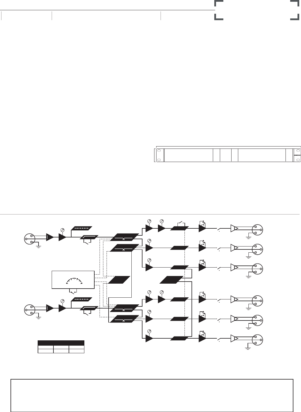
3 WAY STEREO / 4 WAY MONO XOVER
Modes
Stereo 2 Way
Stereo 3 Way
Mono 4 Way
Mono 4 Way Low
Operating Frequencies Ch 1 A
35Hz to 800Hz X1 or 350Hz to 8KHz
35Hz to 800Hz X1 or 350Hz to 8KHz
35Hz to 800Hz
18Hz to 400Hz
Operating Frequencies Ch 1B
350Hz to 8KHz
350Hz to 8KHz
350Hz to 8KHz
175Hz to 4KHz
Operating Frequencies Ch 2 A
35Hz to 800Hz X1 or 350Hz to 8KHz
35Hz to 800Hz X1 or 350Hz to 8KHz
Operating Frequencies Ch 2B
350Hz to 8KHz
350Hz to 8KHz
350Hz to 8KHz
700Hz to 8KHz
S•3 -wAy
ARCHITECT’S & ENGINEER’S SPECIFICATIONS
The S 3 Way from Samson shall be a selectable stereo 2-way,
stereo 3-way, or mono 4-way crossover. All rear panel inputs
and outputs shall be on XLR connectors. There shall be a front
panel power switch and rear panel IEC connector for AC main
power. In the center main section there shall be a global operation
2 way, 3 way, 4 way mono, and 4 way low mode select rotary
control, a lighted CD horn EQ push button, lighted Mono sub push
button, lighted limiter push button and rotary limiter threshold
control. All variable controls have LED indicators to determine
the controls in use and function depending on mode of operation.
Each frequency divided output shall have a front panel lighted
mute button and lighted phase switch. Each channel shall have
an input gain control with 4 segment LED metering. Each low
frequency section shall have a variable delay from 0 to 2 mS for
sub cabinet alignment and a level control. On channel one the
low to mid frequency shall be variable from 18Hz to 400Hz with
a times 10 range switch for 35Hz to 8kHz control. The Mid and
high output sections shall have level controls and a mid to high
variable crossover control from 175Hz to 4kHz with a times 10
switch for 350Hz to 8kHz operation. On channel 2 the low to mid
frequency shall be variable from 35Hz to 800Hz with a times
10 range switch for 350Hz to 8kHz control. The Mid and high
output sections shall have level controls and a mid to high variable
crossover control from 350Hz to 8kHz with a times 10 switch for
700Hz to 8kHz operation. Channel two shall differ from channel
one for 4-way and 4-way low operation.
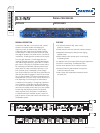
PRODUCT SPECIFICATION SHEET
SERIES DESCRIPTION CATEGORY
S•CLASS SIGNAL PROCESSORS PROCESSORS
Inputs .........................................Female balanced XLR
Impedance ......................................Balanced >15kΩ
Max. Input level ..............................+26 dBu balanced
Output ......................................... Male balanced XLR
.........................................Impedance balanced 100Ω
Max. Output Level ...........................+26 dBu
Frequency Response ........................<10 Hz to >90 kHz, +0/-3 dB
Power Inlet ..................................... Standard IEC receptacle
with fuse
× D × H) .................... 1.75˝ × 19˝ × 8.5˝
44.5mm × 482.6mm x 217mm
........................................... 6.6 lbs • 3 kg
•3-way
S
v
v