


Setting Up and Using Your PG Series
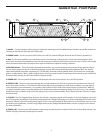
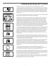
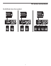
Bridge / Stereo / Parallel switch
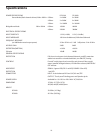
Output connectors
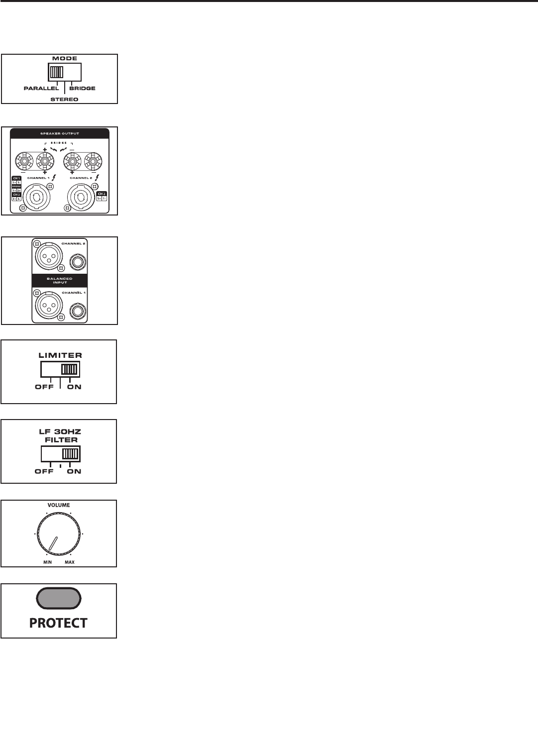
Input connectors
Protection LED
Channel Input control
Setting up your PG Series is a simple procedure which takes only a few minutes:
1. Remove all packing materials (save them in case of need for future service) and decide
where the amplifier is to be physically placed—it can be used free-standing or mounted in
a standard 19” rack, requiring only two rack spaces. When installed, make sure that both
the front and rear panels are unobstructed and that there is good ventilation around the
entire unit (we recommend the use of spacer panels, especially if multiple amplifiers are
used in a rack.
2. Set the rear panel Bridge/ Stereo / Parallel switch as desired (see the “Bridge and Parallel
Modes” section on page 9 in this manual for more information).
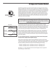
3. Make the speaker connections, using the banana, or Speakon™ output connectors on
the rear panel. It is never a good idea to power up any amplifier that is not connected
to loudspeakers. When operating in Stereo or Parallel mode, any loudspeakers with a
minimum impedance load of 2 ohms (that is, 2 ohms or greater) can be used; however,
in Bridge mode, 4 or 8 ohm speakers must be used. Be sure to connect the loudspeaker
correctly. In Stereo or Parallel mode, make sure the red (+) terminal is connected to the
positive input of the speaker and the black (ground) terminal is connected to the negative
input of the speaker. See page 9 in this manual for more information about Bridge mode
and pages 10 - 11 in this manual for full speaker interconnection instructions.
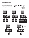
4. Next, make the signal input connections, using the XLR or 1/4-inch TRS input connectors
on the rear panel (if operating the PG Series in Bridge or Parallel mode, use the Channel
1 input only—see page 9 in this manual for more information). If your mixer or crossover
network has balanced outputs, we recommend the use of three-conductor cabling and
connectors (unbalanced two-conductor plugs can also be inserted into the 1/4-inch
TRS inputs, but you’ll get better signal quality and less outside noise and hum if you use
balanced lines).
5. For most applications, we recommend that you set the built-in Limiter switch to “ON”,
which will help protect your speaker system and help keep your signal clean. The Limiter is
a dynamic gain control; essentially a compressor with a fixed ratio of greater than10: 1 and
with its threshold level set just before clipping.
6. The PG series includes a Low Frequency filter, which you can use to roll off the extreme
low frequency content below 30 Hz. Most two–way loudspeakers do not produce a
usable frequency response under 30 Hz, so if you set the Low Frequency filter to the “ON”
position, the amplifier will run cooler and more efficiently. We recommend setting the Low
Frequency filter to “ON” for most all applications except when using the amplifier to power
a subwoofer.
7. On the front panel of the PG Series, turn both Channel input controls fully
counterclockwise (to their “MIN” setting). Then connect the supplied heavy-gauge 3-pin
“IEC” cable to the rear panel IEC connector and to any grounded AC socket.
Because of the relay protection circuitry built into the PG Series, you can even plug it into
the same power strip that other audio devices (such as a mixing console) are connected to.
You can then turn on all devices at once with the single power strip on-off switch, with no
danger of damaging connected speakers by generating “thumps.”
8. Press the front panel Power switch in order to turn on the PG Series. The Power LED will
light and the Protection LED will go on. After approximately five seconds, the Protection
LED will go off (you’ll hear a click when this occurs).
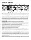
Limiter
Low Frequency Filter
5