


11
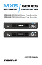
MXS Series Power Amplifiers
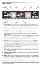
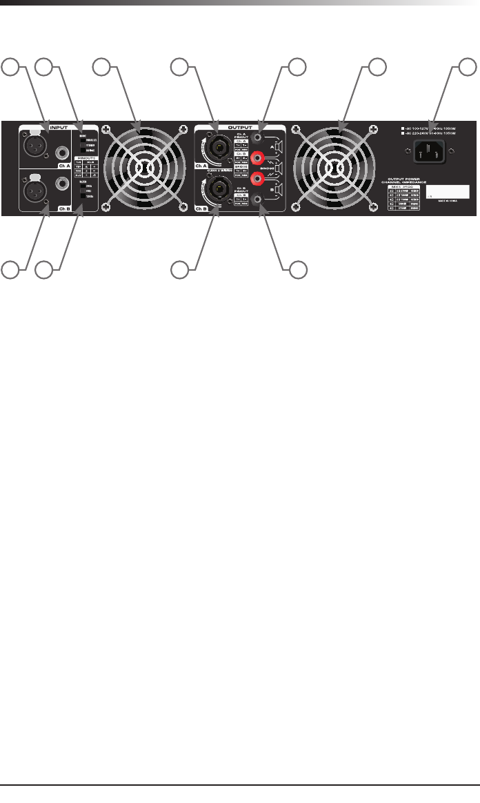
Rear Callouts
1 3 4 46 75
1 2 5 6
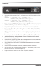
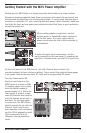
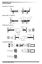
1. Input Connectors - Connect incoming signals to these electronically balanced con-
nectors, using either XLR or ¼” TRS (Tip/Ring/Sleeve) plugs. The amplifier accepts
input levels of any strength but needs at least +4 dBu to achieve maximum power.
The inputs are wired in parallel, so they can be used to daisy chain out of each
channel to a second power amplifier.
2. FILTER Switch - This switch selects the setting of the internal high-pass filter on
the audio outputs. When set to the FULL position, the filter is bypassed and the
amplifier passes the full frequency bandwidth (20Hz to 20kHz) to each output
channel. In the
28Hz position, it sets a high-pass filter at 28Hz on the speaker outputs. This setting
is useful for protecting speakers from over-excursion. The 120Hz position sets a
high-pass filter at 120Hz on the speaker outputs. This setting can be used as a
crossover for satellite speakers when adding subwoofers to your audio system.
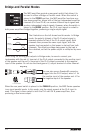
3. MODE Switch - For normal operation, place this three-way switch in the STEREO posi-
tion. When placed in the PARALLEL position, the signal arriving at the Ch A input
only is routed to the power amplifiers of both Ch A and Ch B (the Ch B input is
ignored). When placed in its BRIDGE position, the signal arriving at the Ch A input
only is again routed to both power amplifiers (the Ch B input is ignored), but the
two power amplifiers are bridged together.
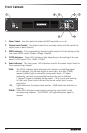
4. Exhaust Fan - This variable-speed fan provides cooling to amplifier. Make sure that
both the front and rear panels are kept free of all obstructions and that cool, fresh
air is accessible at all times.
5. Speakon® Output Connectors - Use these to connect each channel of the amplifier to
your loudspeakers.
6. Binding Post-Use these to connect each channel of the amplifier to your loudspeak-
ers. Be sure to connect the loudspeaker correctly, with the red (+) terminal normally
connected to the positive input of the speaker and the black (ground) terminal nor-
mally connected to the negative input of the speaker.
7. AC Input - Connect the supplied heavy-gauge 3-pin “IEC” power cable here