6
Controls and Functions
MONO/STEREO INPUT CHANNEL SECTION
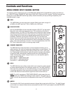
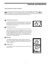
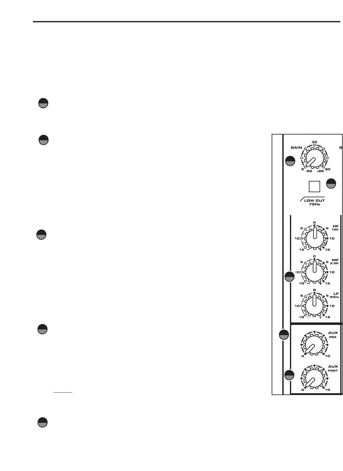
The following section details each part of the MDR1064’s MONO INPUT CHANNELS including the GAIN con-
trol, LOW CUT switch, 3-BAND EQ, AUX sends, PEAK LED, PAN and LEVEL controls. The input channels one
through six on the MDR1064 feature high quality, discrete transistor pre-amp providing transparency and
extended dynamic range.
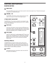
GAIN
The MDR1064’s pre-amp stage has a variable GAIN control with a range of 5
to 60dB on the MIC input and –26 to +26dB on the LINE input.
LOW CUT FILTER
Each of the MDR1064’s first six channels include a LOW CUT (or high pass)
filter which rolls off the low frequencies from 75Hz and below at the rate of
18dB per octave. The LOW CUT filter allows you to remove the lower frequen-
cies that you sometime just don’t want to pick up. For example, when you are
miking a high-hat you only want to capture the frequencies that the hi-hat is
producing. Therefore, by using the LOW CUT filter, you can reduce the
amount of pick-up from the low toms and bass drum that may leak into the hi-
hat mic. You can use the same technique on other instruments like acoustic
guitar, violin, piano and even on vocals. In live sound applications, the LOW
CUT filter is especially useful for removing stage rumble.
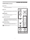
CHANNEL EQUALIZER
The MDR1064 input channels feature a 3-band equalizer allowing you to
adjust the high, mid, and low frequencies independently on each channel. The
channel’s frequency response is flat when the knobs are in the "12:00" posi-
tion. Rotating the knob towards the right will boost the corresponding frequen-
cy band by 15dB, and rotating it towards the left will cut the frequency by
15dB. The frequency centers, range of boost or cut, and equalizer type for
each band are as follows:
High: 12KHz +/- 15dB shelving type
Mid: 2.5KHz +/- 15dB peaking type
Low: 80Hz +/- 15dB shelving type
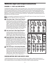
AUX 1
The MDR1064 has two auxiliary sends which can be used for sending signals
to external effects devices or for creating a monitor mix. The AUX1 section is
often used for a monitor mix in a live sound mixing, or for a headphone mix in
a recording application. Each input channel includes an AUX 1 send which
controls the amount of that channel’s signal that is sent to the AUX bus.
NOTE:
The AUX1 controls are "PRE-FADER SENDS" which means they are
not affected by the FADER level settings of each channel. This allows you to
create a mix for the monitors that is independent of the main LEFT and RIGHT
MIX.
AUX 2
The channel’s AUX 2 knob controls the amount of signal that is sent to the AUX 2 bus. The AUX 2 signal
can be sent to an external effects device connected to the AUX 2 OUT jack located in the MASTER SEC-
TION jack field.
1
2
4
5
1
2
4
5
3
3


