


ENGLISH
5
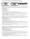
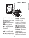
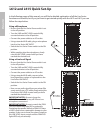
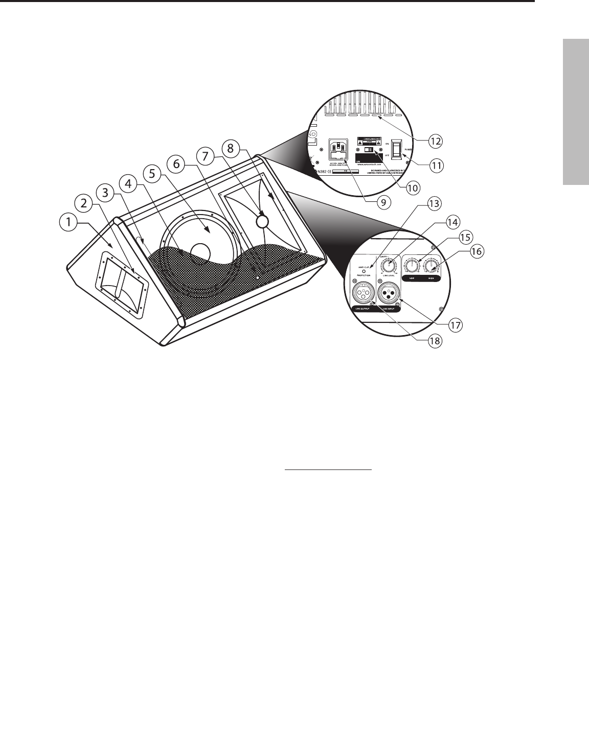
L612M Layout
1. Enclosure – Rigid, all-plywood enclosure for maxmum
output and durability.
2. Handle – Oversize carry handle.
3. Bass Port– Precision tuned, low frequency port
extends the bass response.
4. Steel Grill – Durable steel grill provides protection
5. Low Frequency Driver - 12-inch woofer with oversize
motor and 3-inch voice coil deliver deep, controlled
bass response.
6. Power LED – Blue Light Emitting Diode illuminates
indicating the unit is powered on and ready for
operation.
7 Titanium Compression Driver – 1.75 inch (44mm),
titanium diaphragm with 1 inch opening.
8. Wide Dispersion Horn
– 1 inch throat, 60 x 90 degree
wide dispersion horn provides extensive coverage and
linear off- axis response.
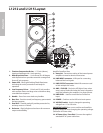
Amplifier Panel Rear View
9. AC Power inlet / Fuse Sled – Connect the supplied
standard IEC AC power cable here.
10. VOLTAGE switch - Used to change the operating
voltage from 115 to 230 volts.
IMPORTANT NOTE! Bure sure to confirm and install the
properly rated fuse when changing the operating voltage.
(See above AC Power Inlet).
11. POWER – Switches on the L612Ms main power.
12. Heat sink - Convection cooling of the internal power
amplifier via massive aluminum extrusion.
Amplifier Panel Side Viewv
13. AMP / CLIP LED - Dual color LED lights Green when
amp is active, flashes Red when the amp is clipped or
stays Red indicating the amplifier is in protect mode.
14. LINE LEVEL – Used to control the level of the line
input.
15. LOW FREQUENCY - Controls the low band of the
Channel Equalizer, +/- 12 dB at 100Hz.
16. HIGH FREQUENCY - Controls the high band of the
Channel Equalizer, +/- 12 dB at 10kHz.
17. LINE INPUT connector - XLR Input for connecting
balanced line level signals.
18. LINE OUTPUT connector- Male XLR connector used
to link multiple L612M’s.