


11
Expedition EX30
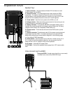
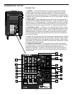
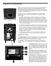
5: Insert (sub) connector - This 1/4" connector brings line-level signal in directly before the
EX30 power amplifiers. It is normally used to return signal from an optional EX500 subwoofer.
6: Line inputs - Use these 1/4" jacks to connect line-level sources to the EX30. Channels 1 and
2 are mono 1/4" connectors; channel 3/4 uses a stereo (TRS) 1/4" connector, with tip carrying left
signal and ring carrying right signal. Stereo devices should always be connected to the stereo
channel (channels 3/4). If a wireless receiver is connected to the EX30 via its internal
connectors (see page 14 in this manual), its output arrives at channel 2, which can also carry
another line-level source connected to its line input, as well as signal from a microphone
connected to its mic input. If an optional TD30 cassette player is installed, its output arrives at
channels 3/4, which can also carry another two line-level sources (one connected to its line input
and a second connected to the CD inputs [see #15 on the following page]), as well as signal from
a microphone connected to its mic input.
7: Mic inputs - Use these XLR jacks to connect microphones to the EX30’s built-in mic
preamps. Each channel can carry both one or more line level sources (see #6 above) as well
as a mic source.
8: DSP Effects control - Use this to select one of six reverb presets (Small Hall, Medium Hall,
Large Hall, Church, Stadium, or Plate). If you don’t want to hear any reverb, set this switch to the
“Off” position.
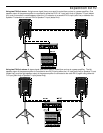
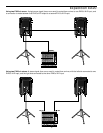
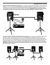
9: Mono/Stereo switch - When using one EX30, set this switch to “Mono” so that the EX30
power amp receives signal from both the left and right output sections. When using multiple
Expedition speaker enclosures, set this switch to “Stereo”; the EX30 will then reproduce only
signal from the left output section only (that is, signals panned left at the mixer); the Right output
can then be used to send signal from the right output section (that is, signal panned right at
the mixer) to a second enclosure. See the interconnection diagrams on pages 10 - 11 for more
information.
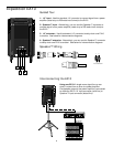
10: Outputs - The dual XLR connectors carry line-level output signal from the EX30. They are
used to send signal to a second EX30 (or EX20) being daisy-chained (see the interconnection
diagram on the following page) or to an optional EX500 subwoofer. Note that the signal being
output from these connectors is dependent upon the setting of the Mono/Stereo switch (see #9
above). When set to “Stereo,” the Left XLR connector carries left signal only and the Right XLR
connector carries right signal only; when set to “Mono,” both the Left and Right connectors carry
the same monophonic signal, summed from both the left and right output sections. See the
interconnection diagrams on pages 10 - 11 for more information.
11: Main Volume control - This knob determines the final output signal level—you can think of
this as being the “master fader.” Signals from all four channels are routed here just before being
routed to the EX30’s built-in power amplifiers and Left and Right output jacks (see #10 above).
12: Battery VU meter - If an optional RB 2030 rechargable battery pack is installed, this meter
shows how much battery power remains as it is being charged (Power switch off) or depleted
(Power switch on). See #20 on the following page.
13: Output VU meter - This three-segment bar meter shows the continuous output level of the
EX30. For optimum signal-to-noise ratio, try to adjust all channel and main Volume controls so
that program material is usually at or around 0 VU, with occasional but not steady excursions to
the red “+3 dB” segment.
14: Limiter LED - Lights whenever the built-in limiter is active. If you see this lighting frequently,
it means you’re overloading the EX30, so turn down one or more of the Channel volume controls
(see #4 on the preceding page) or the main Volume control (see #11 above).