


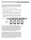
Guided Tour
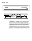
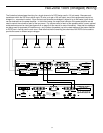
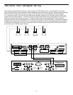
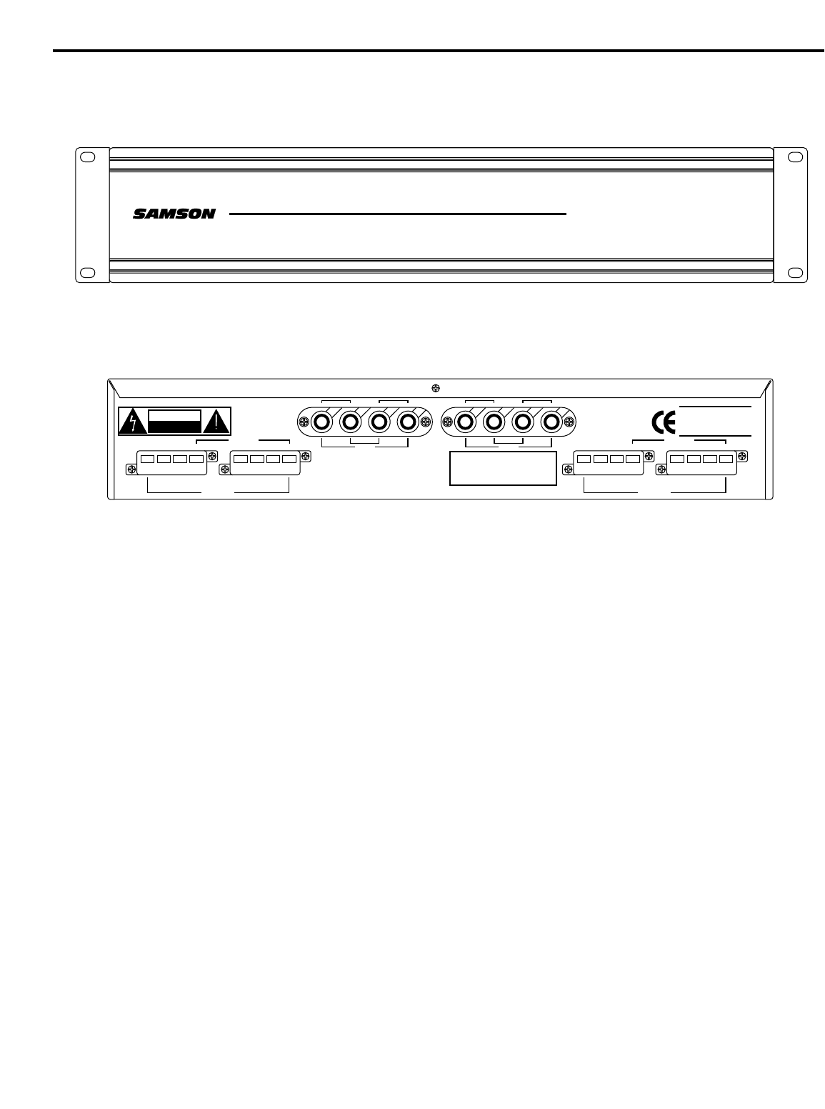
1: Channel inputs (1 - 4) - Connect output signal from a power amplifier to these four
sets of binding post input connectors, making sure to follow the polarity markings
silk-screened above each connector. When using the DS70 in two-zone (bridged)
modes of operation, a bridge connection must be physically made between two channel
inputs as silk-screened on the rear panel (i.e., between the negative terminal of the odd-
numbered channel and the positive terminal of the even-numbered channel). See the
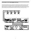
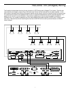
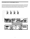
wiring diagrams on pages 6 and 7 in this manual for more information.
2: Channel outputs (1 - 4) - These four sets of screw terminal output connectors are
used to send signal from the DS70 to speaker transformers and loudspeakers. When
using the DS70 in two-zone (bridged) modes of operation, a bridge connection must be
physically made between two channel ouputs as silk-screened on the rear panel. See
the wiring diagrams on pages 6 and 7 in this manual for more information.
4
4 X 120W
4 X 120W
ATT 70
TT 70
VOL
OL
T SPEAKER DISTRIB
T SPEAKER DISTRIB
UTION SYSTEM
UTION SYSTEM
DS70
COMCOM25.2V70V
CH1 OUTPUT
COMCOM25.2V
NC100V
70V
140V
CH2 OUTPUT
SAMSON
SAMSON TECHNOLOGIES CORP.
SPEAKER DISTRIBUTION SYSTEM
INPUT
+
–
–
+
CH3 CH4
INPUT
+
–
–
+
CH1 CH2
BRIDGE
BRIDGE
BRIDGE 70V
COMCOM25.2V70V
RISK OF ELECTRIC SHOCK
DO NOT OPEN
CAUTION
AVIS
RISQUE DE CHOC ELECTRONIQUE
NE PAS OUVRIR
DO NOT EXPOSE THIS EQUIPMENT
TO RAIN OR MOISTURE
SERIAL NUMBER
DS70
SPEAKER DISTRIBUTION
BRIDGE 100V
CH3 OUTPUT
NC100V
140V
CH4 OUTPUT
BRIDGE 100V
COMCOM25.2V70V
BRIDGE 70V