


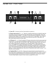
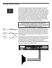
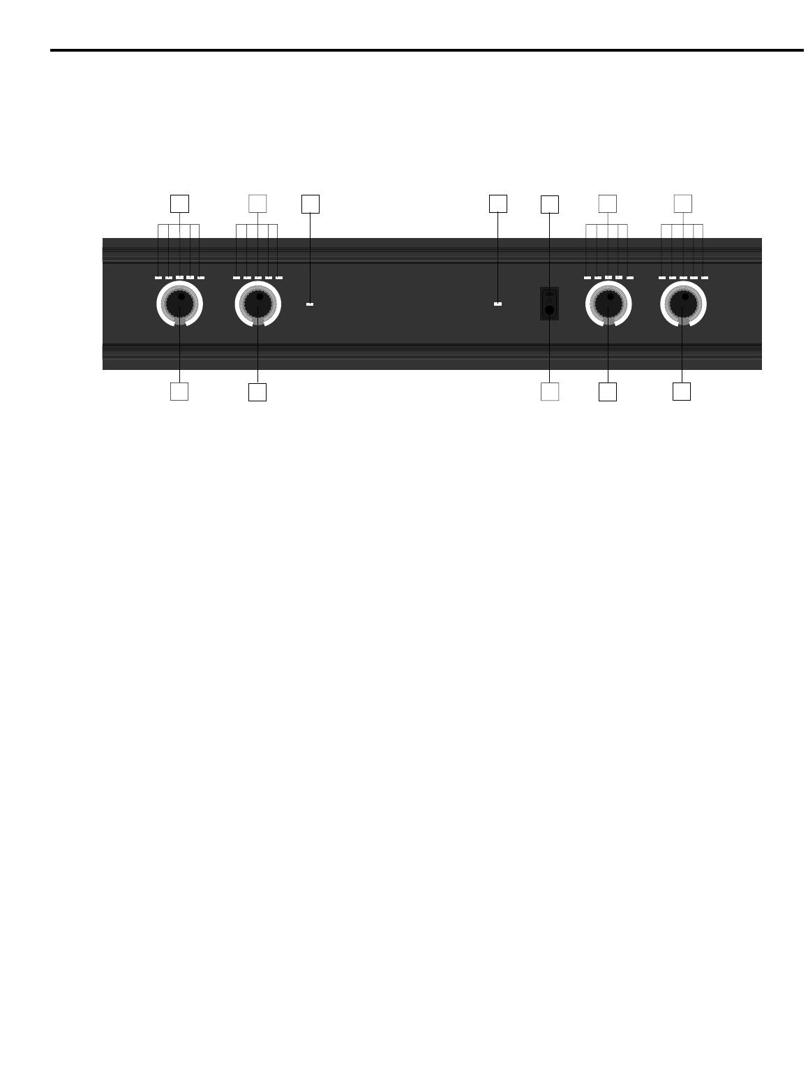
Guided Tour - Front Panel
1: Power switch - Use this to power the Servo Quad Amplifier on or off.
2: Power LED - Lit whenever the Servo Quad Amplifier is powered on.
3: Channel input controls (Ch 1 - 4) - These four 41-position knobs allow you to adjust the input level
of the signal arriving at the rear-panel input jacks (see #4 and #5 on the following page). At their fully
counterclockwise position (labeled “∞”), the signal is infinitely attenuated (completely off). At their fully
clockwise position (labeled “0 dB”), the signal is at unity gain (that is, no attenuation). When 0 dBm of
signal arrives at the input jacks and the Channel Input controls are set to their “0 dB” position, the
Servo Quad Amplifier delivers full power output.
4: LED meters (Ch 1 - 4)- These five-segment LED meters continuously monitor the power output level
for that channel. For convenience, the segments are labeled as follows, from left to right: -20 dB / 10%,
-10 dB / 30%, -3 dB / 50%, 0 dB / 70%, and CLIP / 100%. When the left-most (-20 dB / 10%) segment
is lit, the Servo Quad Amplifier is operating at 10% of its power capacity. When the right-most
(CLIP / 100%) segment is lit, signal is being output at full strength. For the best signal-to-noise ratio,
the right-most (CLIP / 100%) segment should light occasionally during peak levels; if it lights frequently,
you may be overloading the Servo Quad Amplifier and a distorted (“clipped”) signal is probably being
output. If this occurs and backing off the Input Level control delivers too low an output level for your
application, consider using bridge stereo mode (see the “Bridge Stereo Mode” section on page 7 in this
manual for more information).
5: Protection LEDs (Ch 1/2, Ch 3/4) - These go on for approximately five seconds whenever the
Servo Quad Amplifier is powered on and fade slowly when the amp is powered off. When lit, 0 volts DC
are provided to all connected speakers, thus muting them and preventing any “thump” from occurring.
For a complete description of the conditions under which this light goes on, see the section entitled
“The Servo Quad Amplifier Protection Circuitry” section on page 6 of this manual.
5
SAMSON
SERVO 4120 - 120 WATT X 4 AMPLIFIER
LEVEL
-16
-19
-23
-27
-33
-40
-44
∞
0dB
-0.5
-3
-5
-9
-12
-1
5
CHANNEL 1
LEVEL
-16
-19
-23
-27
-33
-40
-44
∞
0dB
-0.5
-3
-5
-9
-12
-1
5
CHANNEL 2
LEVEL
-16
-19
-23
-27
-33
-40
-44
∞
0dB
-0.5
-3
-5
-9
-12
-1
5
CHANNEL 4
LEVEL
-16
-19
-23
-27
-33
-40
-44
∞
0dB
-0.5
-3
-5
-9
-12
-1
5
CHANNEL 3
CH1/2
PROTECTION
CH3/4
PROTECTION
POWER
10
30 50 70 100%
-20 dB-10 dB -3 dB 0 dB CLIP
10
30 50 70 100%
-20 dB-10 dB -3 dB 0 dB CLIP
10
30 50 70 100%
-20 dB-10 dB -3 dB 0 dB CLIP
10
30 50 70 100%
-20 dB-10 dB -3 dB 0 dB CLIP
3
3
3
3
4
4
4
4
1
2
5
5