


6 Russound R290DS Installation Manual
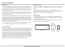
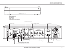
The R290DS has dual source capability. If two sources are used, connect the
source you want to have priority to the Primary input and the other source to
the Secondary input.
Whenever the Primary source is active, that signal will take priority over the
distributed audio signal on the Secondary line. The signal is still active on the
Secondary line, and once the Primary audio signal is muted or turned o the
R290DS will automatically switch back to the Secondary audio signal.
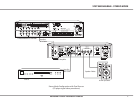
Stereo Mode
The R290DS can be congured as a power upgrade for specic zones, for
use with large speaker selectors, and for long parallel speaker runs (outdoor
zones)
Unplug the R290DS.1.
Set the Stereo/Bridge switch to Stereo.2.
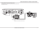
Connect the audio line output from a stereo preamplier or source to 3.
the left and right Primary input jacks of the R290DS. If the output is only
available as speaker level see Speaker Level Signal at right.
Connect the audio line output from the secondary source to the Secondary 4.
input jacks in the same manner.
Connect your speakers to the terminals, observing proper polarity.5.
Restore power to the amplier. Both channel levels can be adjusted with 6.
the corresponding channel level adjustments.
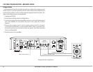
Dual source connections
Connect the source audio outputs to both Primary and Secondary inputs as
instructed above.
Set the delay with the Delay Time knob. The Delay Time adjustment determines
when the switch back to the Secondary signal will occur. Example: If the primary
source is a CD changer, increasing the delay time will prevent a switch back to
the secondary source while the disc is changing.
Note: This works with all incoming signals, line level or speaker level.
SYSTEm CONFIGURATION - STEREO mODE
Speaker Level Signal
If either of the sources is only available as a speaker level signal, connect it to
the Speaker In terminals, using the screw down terminal block and observing
proper polarity. Only one set of speaker level inputs can be utilized and assigned
by the selector switch.
Set the switch to Primary or Secondary.
Only one type of input (speaker or line) should be assigned to each line. For
typical connectivity, do not set speaker input switch to Primary and make
connections to the Primary line input.
Note: If there are two inputs assigned as Primary (Speaker and Line) the Line
input will take priority.
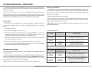
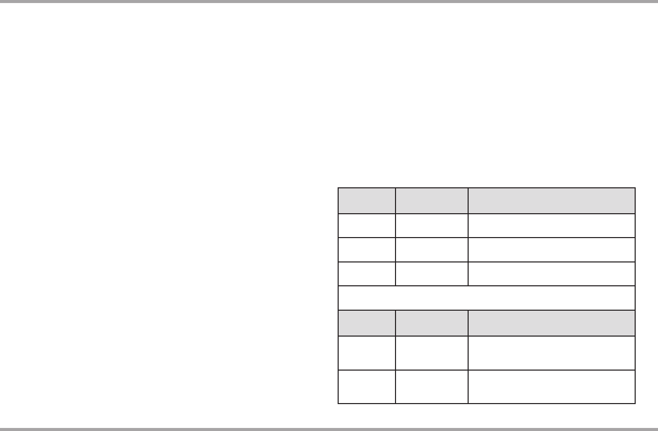
Typical Connections
Line Input
Speaker Input
/ Switch Position
Audible Output
Primary /
Secondary
n/a
Primary if signal present
Secondary if no Primary signal
Primary
Secondary
/ Secondary
Primary if signal present
Secondary if no Primary signal
Secondary
Primary
/ Primary
Primary if signal present
Secondary if no Primary signal
Connections for Unique Solutions
Line Input
Speaker Input
/ Switch Position
Audible Output
Primary /
Secondary
Primary
/Primary
Primary Line Input if signal present
Speaker Input if no Primary Line signal
Secondary if no Primary Line or Speaker signal
Primary /
Secondary
Secondary
/Secondary
Primary Line Input if signal present
Secondary Line Input if no Primary signal
Speaker Input if no Line signal