


1. Description
The PRO and PRO-VC series speaker selectors are highly efficient dual-source, impedance-matching selectors. These high-quality
speaker selectors are designed for use with either 4 Ohm or 8 Ohm amplifiers and 4 Ohm to 8 Ohm speakers. In addition to speaker
selection, the PRO-VC units include a volume control on the number 1 pair of speakers.
The PRO and PRO-VC speaker selectors are equipped with a low-frequency protection circuit to reduce subsonic signals. This allows
high power operation without amplifier shutdown. The PRO and PRO-VC units employ audiophile-grade impedance matching auto-
formers to maintain a safe operating load at the amplifier while distributing maximum power through the system. Autoformers are very
efficient because of the small loss incurred as a result of heat dissipation. Both series are equipped with a back panel rotary switch,
which is used to set the appropriate impedance based on the number of pairs of speakers connected. This switch selects the proper taps
of the autoformers, allowing all of the amplifier’s power to be delivered to the speakers.
The PRO and PRO-VC speaker selectors can be connected to one or two amplifiers. A front panel button allows switching between the
two amplifiers for all speakers connected to the unit.
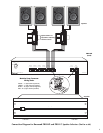
2. Connections
The PRO and PRO-VC series have removable modular snap connectors that provide color-coded wire terminations without the need
for set-screws. Strip about 3/8” of insulation from the ends of all wires to be connected. If necessary, twist the exposed conductor to
insure that no loose strands exist. Remove the AMP A connector by firmly pulling it out of its 4-pole connector. Lift the wire locking
lever on connector. Insert the wires from amplifier A output, being careful to observe the polarity, then lower the lever with a “snap.” In
the same way, connect the amplifier B output to the AMP B connector. Follow the same procedure to connect each pair of speakers to
the appropriate SPEAKER connector, observing proper channel and polarity. If external volume controls are used, connect speaker wire
from the appropriate speaker connector on the PRO/PRO-VC to the volume control input. Speaker connections can support multiple
speaker pairs wired in parallel or series, provided their combined impedance is a minimum of 4 ohms.
3. Operation
To ensure safe operation of the amplifier, an impedance level must first be selected using the rotary switch labeled SPEAKER PAIRS
located on the rear of the unit. This switch should be set to the total number of speaker pairs being connected to the unit. Set the switch
based on the following conditions:
• If the amplifier and the speakers are both 4 ohms, set the rotary switch to the number of pairs of speakers connected to the
PRO/PRO-VC.
• If the amplifier and the speakers are both 8 ohms, set the rotary switch to the number of pairs of speakers connected to the
PRO/PRO-VC.
• If the amplifier is 8 ohms and the speakers are 4 ohms, set the rotary switch to TWICE the number of pairs of speakers connected to
the PRO/PRO-VC.
• If the amplifier is 4 ohms and the speakers are 8 ohms, set the rotary switch to HALF the number of pairs of speakers connected to
the PRO/PRO-VC.
After setting the proper impedance level, the speakers can be turned on and off in any combination.
To switch between the A and B amplifiers, push the AMP A / AMP B button located on the front panel.
PRO-VC: The Speaker 1 volume control feature of the PRO-VC allows volume adjustment for the speakers connected to the first (speak-
er 1) position on the unit. This feature is designed to operate with systems where the main pair of speakers are in the same room as the
speaker selector. Set the receiver’s volume once, and then adjust the volume in the main room with the PRO-VC. The volume level of
the remaining speakers should be adjusted using additional volume controls.
4. Setting System Volume
It is important to properly adjust an impedance-matching system to avoid distortion or DC clipping (DC voltage will be produced from
an amplifier that is overworked or that has an improper load). These can cause an amplifier/receiver to go into protection, and can
cause autoformers on volume controls to heat up, damaging system components. To set up the system, the amplifier/receiver volume
should be at its lowest setting, and the in-wall/selector volume control should be at the highest setting. Slowly adjust the
amplifier/receiver volume to a level that is acceptable for the amplifier to produce without clipping.
2