19
HOW – Final Assembly of Speakers
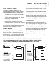
HOW – FINAL ASSEMBLY OF SPEAKERS
Up to this point in the installation process you have
located and cut the hole, mounted the speaker frame,
run the wires, and connected them to the speaker baffle
and to the amplifier/receiver. Now you will mount the
speaker into the frame and attach the grille.
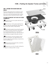
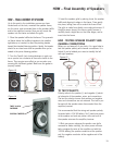
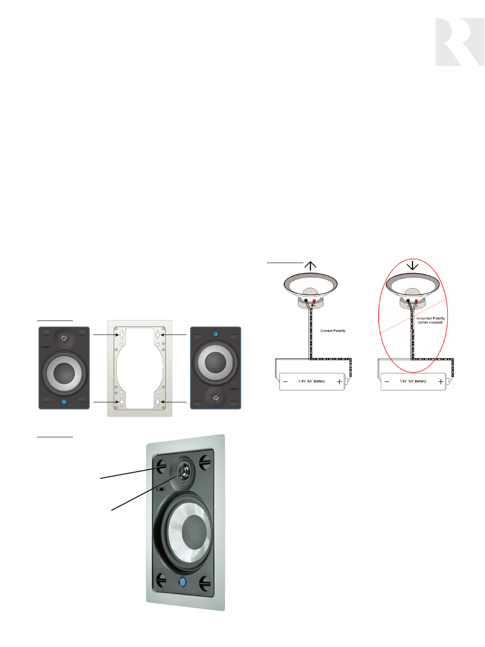
1. Place the speaker baffle into the frame. The symmetri-
cal frame allows the Iso-Mount speaker to be installed
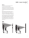
right-side up or inverted, to direct the pivoting tweeter
toward the intended listening position. Ideally, the tweeter
should be as close to ear level as possible when you’re
seated in the prime listening position.
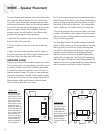
2. Turn the Twist & Lock locking fasteners in each cor-
ner a quarter turn clockwise to secure the baffle to the
frame. They require some effort as you are also com-
pressing the Iso-Mount gasket. Make sure the gasket is
properly seated.
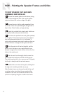
3. Insert the speaker grille by placing it over the speaker
baffle and aligning its edges in the frame. Press gently
into place, taking care not to scratch the frame finish.
The grille is made from pliable, non-rusting aluminum. If
the grille seems loose in the frame, gently remove it,
carefully bend a slight flare on the outer edges, and re-
insert into the frame.
HOW - TESTING SPEAKER POLARITY AND
CHANNEL CONNECTIONS
Before you put away all of your tools, it’s a good idea to
test the speaker polarity and channel connections. It is
helpful if you’ve labeled your wires to identify the left
and right speakers.
TO TEST POLARITY:
Polarity refers to the positive (+) and negative (-) electri-
cal elements of the speakers, wires, and connections.
The test for polarity ensures that positive and negative
wires and connections are not reversed. This test is per-
formed with the speaker wires disconnected from the
amplifier/receiver.
It is recommended that the wiring and speaker polarity
be tested with a 1.5V AA battery. You’ll need one person
at the speaker end and one person at the exit end of
the speaker wire near the amplifier/receiver.
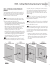
1. While one person observes the woofer cone (grille
removed for better visibility), the other person momen-
tarily energizes the wire at the amplifier end with the
1.5V AA battery (the positive conductor at the positive
end, the negative conductor at the negative end of the
battery).
Figure 13
Figure 14
Figure 15
TWIST & LOCK
FASTENER
PIVOTING TWEETER


