


RM-325 Specications
TW System Specications
DC Operating Limits (station to power supply):
About 5,000 ft. (1.5 km) with #22 AWG wire
Audio Operating Limits (locally powered stations):
About 10,000 ft. (3 km) with low-capacitance cabling
System Capacitance:
0.3 mF, maximum (10,000 ft. [3 km] cable at 30 pF/ft.)
Intercom Channels:
Station Output Level: 0.7 Vrms (0 dBu) nominal
Channel Terminating Impedance: 200W ±5%
Station Bridging Impedance: greater than 10,000W
Current Source:
Transfer Ratio: 3.3 mA/V = 3.3 milliseconds
Output: ±5 mA into 200W, ±1 Vpeak (limiter threshold)
Call Signalling:
Send: 20 kHz ±100 Hz, 0.3 Vrms nominal
Receive: 20 kHz ±200 Hz, 100 mVrms
Talk- Off Signalling:
Send: 24 kHz ±100 Hz, 0.3 Vrms nominal
Receive: 24 kHz ±200 Hz, 100 mVrms
RM-325 General Specications
Power Requirements, Channel Powered RM-325:
30 VDC nominal (standard TW line), 45 to 75 mA
Power Requirements, Locally Powered RM-325:
24 VDC nominal, 45 to 75 mA
Environmental Requirements:
Storage: -40°C to 125°C; 0% to 95% humidity, non-condens-
ing
Operating: 0°C to 50°C; 0% to 95% humidity, non-condens-
ing
Dimensions:
1.72” (44 mm) high, 8.2” (208 mm) wide, 8” (203 mm) deep
Weight:
2 lbs 12 oz (1.23 kg)
Noise Contribution:
Less than -75 dB on the line
Common Mode Rejection Ratio:
Greater than 40 dB from the line
Program Input:
Maximum Input Level: 20 dBu
Nominal Input Level: -10 to +8 dBu
Frequency Response: 100 Hz to 12 kHz ±3 dB
Headphone Amplier
Voltage Gain: 30 ±3 dB from the line
Maximum Output: 150 mW into 50W
Frequency Response: 100 Hz to 8 kHz ±3 dB nominal
Output Voltage Level: 8 volts peak-to-peak
Headphone Impedance: 50 to 600W
Sidetone:
20 dB minimum range, adjustable
Microphone Preamplier:
Maximum Voltage Gain: 54 dB
Frequency Response: 100 Hz to 8 kHz, nominal
Input Impedance: 1,000W, balanced
Limiter Range: 30 dB
Total Harmonic Distortion:
Less than 0.2% nominal at Channel output
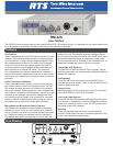
RM-325 Connectors
Auxiliary Connector
Type: DB-15F
Pin 1: Program input low
Pin 2: Program input high
Pin 3: Unswitched mic output high
Pin 4: Foot switch in, channel 1
Pin 5: Foot switch in, channel 2
Pin 6: Local power (+24 VDC)
Pin 7: Remote mic switch in
Pin 8: Not Used
Pin 9: Common
Pin 10: Common
Pin 11: Common
Pin 12: Foot switch channel 1 common
Pin 13: Foot switch channel 2 common
Pin 14: Local power common
Pin 15: Remote mic switch common
CARB MIC Headset Connector
Type: ¼”, 3-Conductor Phone Jack
Tip: Microphone input high (or mic switch contact
Ring: Headphone high
Sleeve: Common
DYN-MIC Headset Connector
Type: XLR-6F 6-Pin Female Audio Connector
Pin 1: Headset dynamic microphone low
Pin 2: Headset dynamic microphone high
Pin 3: Headphone and mic switch common
Pin 4: Headphone left high
Pin 5: Headphone right high
Pin 6: Remote microphone switch contact
Intercom Line Input Connector
Type: XLR-3F 3-Pin Female Audio Connector
Pin 1: Common
Pin 2: Intercom channel 1 audio and power
Pin 3: Intercom channel 2 audio
Intercom Line Loop Connector
Type: XLR-3M 3-Pin Male Audio Connector
Pin 1: Common
Pin 2: Intercom channel 1 audio and power
Pin 3: Intercom channel 2 audio
Program Input Connector
Type: ¼”, 3-Conductor Phone Jack
Tip: Program input high
Ring: Program input low
Sleeve: Common
Ordering Information
RM-325 A5F • 2 channel binaural (stereo) program-
mable modular user station • Catalog Number:
90007491000
RM-325 A4F • 2 channel binaural (stereo) program-
mable modular user station with A4M headset con-
nector • Catalog Number: 90007491001
This specications information is preliminary and is subject to change without notication.
Brand names mentioned are the property of their respective companies.
Contact Information
Telex Communications, Inc.
12000 Portland Avenue South
Burnsville, Minnesota 55337
Telephone: (800) 392-0498
Fax: (800) 323-0498
Form Number: RTS-20352-1
Date: March, 2006