


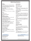

PAM-32 Specications
Ordering Information
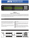
PAM-32
Program assignment monitor
Catalog Number: 90007791000
This specications information is preliminary and is subject to change without notication.
Brand names mentioned are the property of their respective companies.
Contact Information
Telex Communications, Inc.
12000 Portland Avenue South
Burnsville, Minnesota 55337
Telephone: 877·863·4169
Fax: 800·955·6831
Form Number: LIT000040000
Date: April, 2006
General
AC Supply:
External, switching type, 100-240 VAC, 50/60 Hz
with locking DIN connector for attachment to the
keypanel and universal IEC connector for connec-
tion to various AC mains cords.
Environmental
Storage: -40° C to 60° C (-40°F to 140° F)
Operating: -10° C to 41° C (14° F to 105.8° F)
Dimensions
19” (482.6 mm) W x 3” (76.2 mm) H x 3.5” (90mm)
D
Weight
6.44 lbs (2.92 kg)
Mounting Depth Needed
Approx. 7”
Headphone Amplier
Max Voltage Gain: 200dB
Frequency Response: 100 Hz to 10 kHz, ±2dB
Headphone Impedance: 8 to 600
Output Power: 160 mW into 50
Output Voltage Level: 8 Volts peak to peak (max.)
Sidetone Range: 25dB
Speaker Amplier and Speaker
Frequency Response: 100 Hz to 10 kHz, ±2dB
Output Power (per amplier): 4 watts into 4
Output Voltage Level: 11.3 volts peak to peak
(max.)
Volume Control Range: 30dB
Speaker Rating: 4 watts max.
Intercom Inputs (Side A)
Input - Nominal: +8 dBu
Peak: ± 20 dBu max.
AUX Inputs (Side B)
Input Level: + 8 dBu nominal
Connectors (other connector options available)
Headset Connector
Type: 3-circuit, ¼” phone jack with threaded metal
bushing
Pin-out
Tip: Audio side A+
Ring: Audio side B+
Sleeve: Ground
Power Input Connector
Type: 5-pin locking DIN
Pin Out
Pin 1: Common; Pin 2: Common; Pin 3: +5 VDC,
1.50A Max.; Pin 4: -15 VDC, 0.150A Max.; Pin 5:
+15 VDC, 0.5A Max.
Intercom Connectors: Parallel-wired DE9S and
RJ-12 Connectors
Type: DE9S
Pin Out
Pin 1: Data +; Pin 2: Data -; Pin 3: Audio In (from
Matrix) shield; Pin 4: Audio Out (to Matrix) +; Pin
5: Audio Out (to Matrix) (-); Pin 6: Data Shield; Pin
7: Audio In (from Matrix) (-); Pin 8: Audio In (from
Matrix) (+); Pin 9: Audio Out (to Matrix) shield
Type: RJ-12
Pin Out
Pin 1: Data -; Pin 2: Audio In (from Matrix) (+); Pin
3: Audio Out (to Matrix) (+); Pin 4: Audio Out (to
Matrix) (-); Pin 5: Audio In (from Matrix) (-); Pin 6:
Data +
Expansion Connector
Type: RJ-45
LCP Connector
Type: RJ-45
Foot Switch / Speaker
Type: 9-pin male D-Sub
Pin Out
Pin 1: Gnd; Pin 2: Speaker Low (-); Pin 3: Gnd;
Pin 4: No Connection; Pin 5: Foot Switch; Pin 6:
Speaker High (+); Pin 7: No Connection; Pin 8: No
Connection; Pin 9: Gnd
Matrix Out Balanced Output
Type: 3-pin Male XLR
Pin Out
Pin 1: Shield (circuit common); Pin 2: Audio output
+; Pin 3: Audio output -
Note: Output Level +8 dBu nominal (balanced).