


UM10032
ISP1362 OTG add-on eval kit with Intel PXA250/255 IDP rev. 4
UM10032_4 © ST-ERICSSON. All rights reserved.
User manual Rev. 04 — 12 October 2009 7 of 21
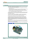
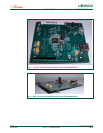
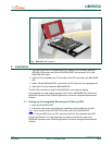
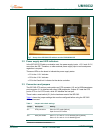
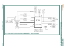
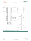
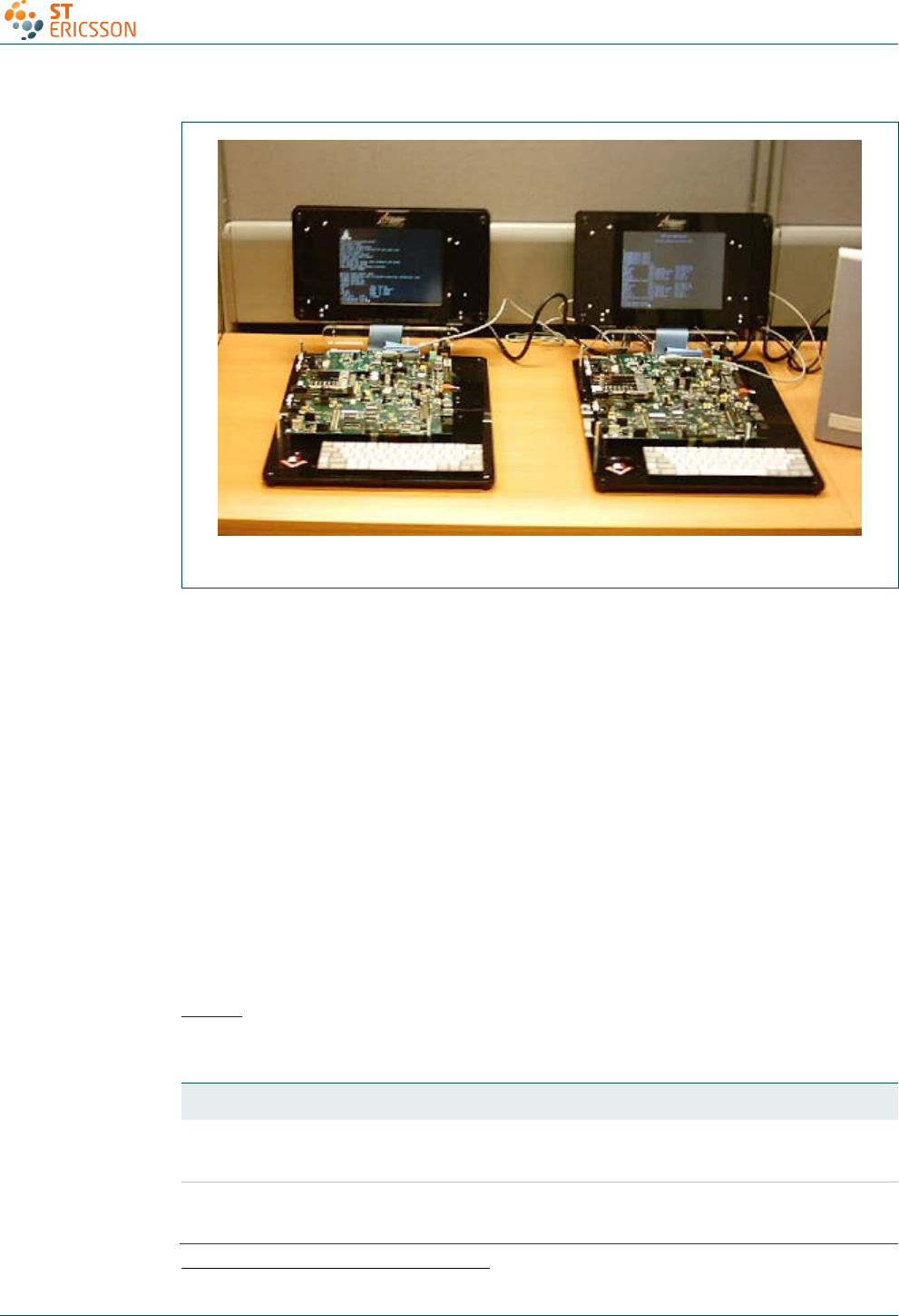
Fig 7. Setup of the ISP1362 OTG add-on card for PXA250/255 IDP
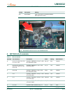
3.2 Power supply and LED indicators
In the ISP1362 OTG add-on evaluation card, the power supply inputs, +3.3 V and +5.0 V,
come from the IDP. Therefore, no other external power supply input or on-board power
regulation is required.
There are LEDs on the board to indicate the power supply status:
• D1 is the +3.3 V indicator.
• D2 is the +5.0 V indicator.
• D3 is the GoodLink1 indicator for the device controller.
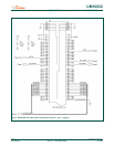
3.3 Connectors and jumpers
The ISP1362 OTG add-on card contains an OTG connector (J2) and a USB downstream
port connector (J1) to interface with other USB peripherals. Jumper JP1 sets the OTG
port to OTG or non-OTG mode, while JP2 disables the host port.
There is also a reset switch (S1) for the hardware reset of the ISP1362.
Table 1
shows the jumper settings that must be configured before using the ISP1362
OTG add-on card.
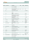
Table 1. Jumper and switch settings
Jumper Description Setting
JP1 OTG port select Short for OTG mode [default]
Open for non-OTG mode
JP2 Host port enable Short <1—3> and <2—4> for enabling port 2 [default]
Short <3—5> and <4—6> for disabling port 2
1
GoodLink is a trademark of ST-Ericsson.