7
English
Computer I/O
[
The RT-1082 can be operated from a computer
with audio system control software from third-
party developers. This control is accomplished
by sending operating codes from the computer
via a hard wired RS-232 serial connection
In addition, the RT-1082 can be updated using
special software from Rotel.
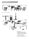
The COMPUTER I/O input provides the neces
-
sary network connections on the rear panel. It
accepts standard RJ-45 8-pin modular plugs,
such as those commonly used in 10-BaseT UTP
Ethernet cabling. For additional information
on the connections, cabling, software, and
operating codes for computer control or updat
-
ing of the RT-1082, contact your authorized
Rotel dealer or Rotel Tech Support.
EXT REMOTE IN Jack
]
This 3.5mm mini-jack receives command codes
from industry standard infrared receivers
(Xantech, etc.) via hard-wired connections.
This feature could prove useful when the unit
is installed in a cabinet and the front panel
sensor is blocked. Consult your authorized
Rotel dealer for information on these external
repeaters and the proper wiring of a jack to
fit the mini-jack receptacle.
12V TRIGGER Connection
\
The RT-1082 can be activated by a 12 volt trigger
signal from a Rotel preamplifier.
The trigger input accepts any control signal (AC
or DC) ranging from 3 volts to 30 volts. When
a cable is connected to the input and a trigger
signal is present, the tuner is activated.
When the trigger signal is interrupted, the tuner
goes into standby mode. The front panel indicator
light remains lit, but the display goes dark and
the unit will not operate.
The RT-1082 will also pass a 12V trigger signal to
associated equipment using a trigger. The signal
will remain 12V in normal operation.
AC Input
a
Your RT-1082 is configured at the factory for
the proper AC line voltage in the country where
you purchased it (120 volts AC at 60Hz in the
USA and 230 volts AC at 50Hz in Europe).
The AC line configuration is noted on a de
-
cal on the back of your unit. Make sure that
your unit is configured properly for your AC
line voltage.
Plug the supplied cord into the AC INPUT
receptacle on the back of the unit. Once all
other rear panel connections are completed,
plug the power cord into an AC wall outlet
or switched AC outlet on another system
component.
Basic Operating Controls
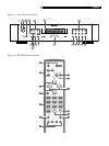
The following explanations will help you get
familiar with the features and controls. When
a function is available on both the front panel
and the remote, a number (see front panel
illustration) and a letter (see remote control
illustration) are shown in the instructions. For
example, to change from the AM to FM band,
you can either press the front panel button or
use the button on the remote. When only one
identifier appears, that control is available
only on the front panel or the remote, but
not both.
NOTE: Controls used for tuning the DAB/
AM/FM receiver are described in the next
sections of this manual.
Standby Button
1
and
Standby LED
2
The STANDBY button is located on the front
panel of the RT-1082 and is not duplicated on
the remote control.
The STANDBY LED will be lit when the AC
input line is connected.
ON and OFF Buttons
A
Remote only
Pressing the ON button deactivates the standby
mode and places the RT-1082 into normal
operation. Pressing the OFF button places the
RT-1082 into standby mode. Power is still sup
-
plied to the unit, but functions are disabled
Remote Sensor
3
This front panel sensor receives infrared signals
from the remote control. Make sure you do
not accidentally block this sensor with cables
or accessories.
Front Panel Display
6
The large fluorescent display in the center por-
tion of the RT-1082 provides status information
used in operating the DAB/AM/FM receiver
(such as station frequency display, band preset
memory, RDS information, etc.).
MEMORY Button
qK
The MEMORY button is used to confirm and
memorize various settings in the setup and
operation of the RT-1082, including tuner
station presets. Its use is described in detail
in the relevant sections below.
ENTER Button
-
Pressing the ENTER button selects the high-
lighted parameter in the SETUP display.
SETUP Button
0
Opens and closes the RT-1082 setup menu.
This provides the RT-1082 setup menus as
well as the ability to change country modes
by using the front panel ENTER, UP/DOWN
BUTTONS.
DIMMER Button
8D
Available on the front panel and remote con-
trol, this button selects four display brightness
settings. Press the button to cycle through the
four settings.
NOTE: When the tuner is turned off then
back on, the display reverts to its normal
setting. The dimmer setting is also available
in the SETUP menu for memory setup until
the AC line is disconnected.


