


12
RKB-2100 Power Amplifier
• With the switch in the SIGNAL
SENSE position, the amplifier turns on
automatically when a signal is detected
at the inputs. The amplifier will go into
standby mode several minutes after no
signal is no longer present. The front pan
-
el power switch overrides this function.
It must be ON for the signal sensing to
work. Turning the switch OFF cuts power
to the amplifier, regardless of whether or
not a signal is present.
• With the switch in the 12V TRIG
position, the amplifier is turned on auto
-
matically when a 12 volt trigger signal is
present at the 12V TRIG input to the left of
the switch. The amplifier goes into standby
mode if the +12 volt signal is not present.
The front panel POWER SWITCH over
-
rides this function. It must be ON for the
+12V trigger to work. Turning the switch
OFF cuts power to the amplifier, regard
-
less of whether or not a trigger signal is
present.
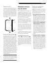
12V Trigger Input
An input jack for connecting the wires car-
rying a +12 volt trigger signal from a Rotel
preamp or surround sound processor to turn
the amplifier on and off. To use this feature
the adjacent slide switch must be placed to
the left position (see previous section).
The TRIGGER INPUT accepts any control
signal (AC or DC) ranging from 3 volts to
30 volts. Using a cable with mono 3.5 mm
mini-plugs on both ends. The +12 V DC sig
-
nal appears at the “tip” connector.
12V Trigger Output
The 12V TRIG jack labeled OUT is used to
pass the remote turn-on signal to a second
Rotel amplifier. Any 12V Trigger signal at
the INPUT jack will be passed through to
the OUT jack.
Circuit Breaker
A 16 amp circuit breaker on the rear panel
protects the amplifier’s electrical circuity.
Generally, the circuit breaker will only open
under a fault condition which results in exces
-
sive current draw. To reset the circuit breaker,
press the button. Should it repeatedly open,
contact your authorized Rotel dealer for trou
-
bleshooting assistance.
Protection Indicator
A thermal protection circuit protects the am-
plifier against potential damage in the event
of extreme or faulty operating conditions. Un-
like many designs, the RKB-2100’s protection
circuit is independent of the audio signal and
has no impact on sonic performance. Instead,
the protection circuit monitors the tempera
-
ture of the output devices and shuts down the
amplifier if temperatures exceed safe limits.
In addition, the RKB-2100 includes overcur
-
rent protection which operates only when
load impedance drops too low.
Should a faulty condition arise, the amplifier
will stop playing and the PROTECTION LED
on the front panel will light.
If this happens, turn the amplifier off, let it
cool down for several minutes, and attempt
to identify and correct the problem. When
you turn the amplifier back on, the protec
-
tion circuit will automatically reset and the
PROTECTION LED should go out.
In most cases, the protection circuitry acti
-
vates because of a fault condition such as
shorted speaker wires, or inadequate ventila-
tion leading to an overheating condition. In
very rare cases, highly reactive or extremely
low impedance speaker loads could cause
the protection circuit to engage.
Signal Connections
The RKB-2100 provides standard conven-
tional input connections — unbalanced RCA
type connections as found on nearly all au-
dio equipment. In addition, there is a pair of
SIGNAL OUTPUT LINK connections for pass-
ing the unchanged input signal on to another
audio component.
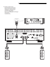
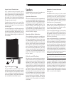
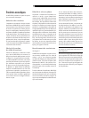
RCA Inputs
See Figure 2
These RCA inputs accept audio signals from
preamplifiers or surround sound processors.
Use high quality audio interconnect cables
for best performance.
Connect the left channel output of your pre
-
amp to the LEFT INPUT on the RKB-2100.
Connect the right channel of your preamp
to the RIGHT INPUT.
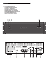
AC Power and Control
AC Power Input
Your RKB-2100 is configured at the factory
for the proper AC line voltage in the country
where you purchased it (USA: 120 volts/60
Hz, Europe: 230 volts/50 Hz). The AC line
configuration is noted on a label on the
back panel.
The RKB-2100 is supplied with the proper AC
power cord. Use only this cord or an exact
equivalent. Do not modify the supplied cord.
Do not use an extension cord.
Be sure the power switch on the front panel
of the RKB-2100 is turned off. Then, plug one
end of the cord into the AC power connector
on the back panel of the amplifier. Plug the
other end into an appropriate AC outlet.
If you are going to be away from home for
an extended period of time, it is a sensible
precaution to unplug your amplifier.
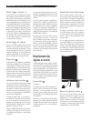
Power Switch
Indicator LED
The power switch is located on the left side
of the front panel. To turn the amplifier on
(or to activate either of the optional auto-
matic power-on modes), push the switch in.
The LED indicator above the switch will light,
indicating that the amplifier is turned on. To
turn the amplifier off, push the button again
and return it to the out position.
Auto Turn On/Off Mode Selec-
tor
The RKB-2100 provides three different op-
tions for manual or automatic power on/off
operation. These modes are selectable us-
ing a three-position slide switch on the back
panel as follows:
• With the switch in the OFF position,
the amplifier is turned on or off manually
using the front panel power switch. Also
use this mode if you are using a switched
AC outlet to control power to the ampli
-
fier.