


9
NOTE: Should you move your RC-1090
amplifier to another country, it is possible
to reconfigure your amplifier for use on a
different line voltage. Do not attempt to
perform this conversion yourself. Opening
the enclosure of the RC-1090 exposes you
to dangerous voltages. Consult a qualified
service person or the Rotel factory service
department for information.
If you are going to be away from home for
an extended period of time such as a month-
long vacation, it is a sensible precaution to
unplug your amplifier (as well as other au-
dio and video components) while you are
away.
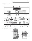
Power/Standby Switch ,
Remote Power Button and
Power Indicator
The Power/Standby switch is located on
the left side of the front panel. When it is
pressed the RC-1090 is turned on and the front
panel displays and indicators are illuminated.
The Power button
on the RR-969 does the
same thing. Pressing the Standby switch or
remote Power button again returns the
RC-1090 in “standby” mode and the func-
tion indicators are turned off. The Power In-
dicator light
above the Standby button is
always illuminated when the RC-1090 is con-
nected to a “live” AC outlet.
NOTE: The RC-1090 will be turned on
and in the normal operating mode as soon
as it is connected to the AC outlet. Be sure
to set the Volume control to the minimum
(full counterclockwise) position before con-
necting the power cord.
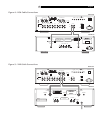
Auxiliary Power Outputs
(North American version only.)
The RC-1090 has two switched outlets on
the back panel. Power is available from these
outlets when the RC-1090 is turned on.
Power to these outlets is turned off when the
RC-1090 is in Standby mode. These outlets
can provide up to a total of 400 watts. They
are appropriate for supplying power to sig-
nal sources, such as CD players, tuners, or
tape decks. They should not be used for
power amplifiers. Connecting components
that will draw more than 400 watts to these
outputs could damage the Standby switch
in the RC-1090.
NOTE: Do not connect the power cord for
a power amplifier to the auxiliary power
outlets on the RC-1090. Power amplifiers
often draw more power than these outlets
can provide.
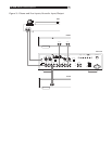
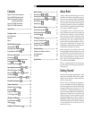
Input Signal Connections
and
[See Figure 3.]
The RC-1090 has conventional RCA-type con-
nectors for all inputs. In addition their is a set
of balanced XLR type inputs for the CD input
for use with high performance CD players that
have balanced outputs.
NOTE: To prevent loud noises that neither
you nor your speakers will appreciate,
make sure the system is turned off when
you make any signal connections.
Phono Input Selector Switch
The Phono input is for a moving magnet (MM)
or moving coil (MC) phono cartridge only and
is incompatible with line level components. Set
the Phono Input Selector Switch as appropri-
ate for the phono cartridge you are using.
Leave the switch button in the out position for
a moving magnet cartridge; push the switch
in for a moving coil cartridge.
Some high output moving coil cartridges are
designed to operate in the moving magnet po-
sition. If you are in doubt about the correct
setting, check the instruction manual for your
phono cartridge for information regarding its
output voltage and the expected input imped-
ance. The Phono input has 47 kOhms input
impedance and 2.5 mV sensitivity in the MM
position and 100 Ohms input impedance and
0.25 mV sensitivity in the MC position. If you
still have questions about the proper setting
of the phono input selector switch, consult your
authorized Rotel dealer.
Phono Input and
Ground Connection
Plug the cable from the turntable into the
appropriate left and right phono inputs. If the
turntable has a “ground” wire connect it to
the screw terminal to the left of the Phono in-
puts. It will help prevent hum and noise.
Line Level Inputs
The CD, Video, Tuner, and Aux inputs of the
RC-1090 are “line level” inputs. These are for
connecting components such as CD players,
Hi Fi or NICAM Stereo video cassette record-
ers, tuners for audio or video, Laser Disc play-
ers or the analog output from a CD ROM drive.
The Left and Right channels are clearly labeled
and should be connected to the correspond-
ing channels of the source component. The
Left RCA connectors are white, the Right con-
nectors are red. Use high quality RCA cables
for connecting input source components to the
RC-1090. Ask your authorized Rotel dealer
for advice about cables.
Balanced CD Selector
Switch and Input
If your CD player has balanced XLR-type
outputs, connect them to the Balanced CD
Inputs
. The Balanced CD Selector Switch
must be set to “On”.
NOTE: Use only one set of the CD inputs
and set the Selector Switch as appropriate.
English