


OPERATION
When the RP503 has been properly connected, ensure the power switch is on
and the Power LED is lit.
MIC PREAMP SETTINGS
For condenser microphones, press in the Phantom Power switch. Press the PAD
switch in if you’re sending a line level (+4dB) signal into the RP503. This helps
prevent overload. Send a signal to the RP503 by checking the microphone or
instrument connected to the INPUT. Adjust the GAIN control while sending the
signal, when the CLIP led lights slightly, back the GAIN control off (counterclock-
wise) one or two marks to achieve the proper level of incoming signal.
COMPRESSOR SETTINGS
Press in the IN/OUT switch to engage the compressor. Begin by setting the
THRESHOLD control high (around 3 o’clock) and the RATIO low (fully counter
-
clockwise). This is a very low compression setting. To increase the amount of
compression, lower the THRESHOLD and increase the RATIO until the desired
amount is achieved.
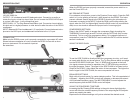
USING THE SIDE CHAIN
To use the SIDE CHAIN to directly access the compressor circuitry, you’ll need
an Insert cable like the one shown above. The Tip-Ring-Sleeve stereo end plugs
into the RP503 SIDE CHAIN jack. The 1/4” SEND plug connects to the Input
of a signal processor such as an equalizer, the 1/4” RETURN plug connects to
the signal processor Output. The signal in the SIDE CHAIN is not heard on the
Output of the RP503, it only effects the action of the compressor. The higher the
level of signal in the SIDE CHAIN, the more compression will occur.
EQUALIZER SETTINGS
Begin with all controls set at 0 or center detente position. This is the equivalent of
a “bypass”. Adjusting the LEVEL controls will increase or decrease the amount
of the indicated frequency range. The MID FREQUENCY control adjusts the
actual frequency that the MID LEVEL control will adjust.
USING THE PROCESSES TOGETHER
Increasing the Mic Preamp GAIN settings to the point where slight distortion
occurs will effect the overall frequency content of the output signal. EQ adjuste-
ments may need to be made.
Experiment with different settings until you’ve acheived the desired sound.
3 4
DESCRIPTION CONT.
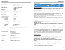
REAR PANEL
120 VAC 50/60 Hz:
OUTPUT: 1/4” unbalanced and XLR balanced output. Connect to an audio re-
corder line input or mixer line input. Note: Do not connect the RP503 XLR Output
to a mixer’s Mic Input - it will overload that input.
SIDE CHAIN: 1/4” Tip-Ring-Sleeve Send\Return jack. Connect an Insert cable to
this jack and to a signal processor or other device to alter the action of the RP503
compressor.
INPUT: Balanced XLR and unbalanced 1/4” Input jacks. Connect balanced micro-
phones to the XLR input, and unbalanced instruments to the 1/4” input.
CONNECTION
Make sure the RP503 power cord is properly connected to a grounded AC outlet.
Shown below are examples of how to connect the RP503 for use with a micro-
phone or instrument. Do not use both inputs at
the same time.